ORDER NEW SAMPLING RATE AND DIGITAL PROCESSING ASSIGNMENT AT NOMINAL PRICE!
Assignment - Lab Questions
Part A -
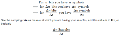
Q1. Give a formula showing how the IQ Sampling Rate, the symbol rate 1 T, and the number of samples per symbol M are related. Determine the value of M for an IQ Sampling Rate of 1 MHz and a symbol rate of 10,000 symbols/s.
Signal is defined as:
sr[n] = I[n]cos(ω0n) + Q[n]sin(ω0n)
which is a bandpass, modulated, narrow band signal where the components I[n]I[n] and Q[n]Q[n] are the lowpass baseband in-phase and quadrature-phase components respectively.Then in order to obtain the I and Q components from sr[n]sr[n] you can apply the following just like the analog case:
hence IQ sampling rate is given as
I[n] = hLP[n]*(sr[n]cos(ω0n))
Q[n] = hLP[n]*(sr[n]sin(ω0n))
Sampling rate, symbol rate and number of symbols per symbol are related as:
IQ=1 MHZ
Symbol rate = 10000 symbols per second
IQ=M/T
Hence
1*1000=M/1000
Hence M=10^6 number of samples per second
Q2. Note that the IQ sampling rate at the receiver is different from the IQ sampling rate at the transmitter. Using a higher IQ sampling rate requires faster digital processing. What is the advantage to using a higher IQ sampling rate at the receiver? (Hint: It has something to do with the action of the PulseAlign(real) and the value of M.)
Examining at a higher recurrence will give you increasingly powerful number of bits (ENOB), up to the furthest reaches of the deceptive free unique scope of the Analog to Digital Converter (ADC) you are utilizing (just as different factors, for example, the simple information transfer speed of the ADC). Anyway there are some significant perspectives to comprehend when doing this that I will detail further.
This is because of the general idea of quantization commotion, which under states of inspecting a sign that is uncorrelated to the examining clock is all around approximated as a white (in recurrence) uniform (in greatness) clamor dispersion. Further, the Signal to Noise Ratio (SNR) of a full scale genuine sine-wave will be all around approximated as:
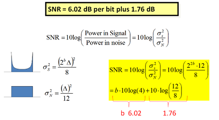
By utilizing a full scale sine wave, we set up a reliable reference line from which we can decide the complete commotion control because of quantization. Sensibly speaking, that commotion power continues as before even as the sine wave abundancy is diminished, or when we use flag that are composites of different sine waves (which means by means of the Fourier Series Expansion, any broad sign).
GET BENEFITTED WITH QUALITY SAMPLING RATE AND DIGITAL PROCESSING ASSIGNMENT HELP SERVICE OF EXPERTSMINDS.COM!
Q3. Compare the rectangular and raised-cosine pulse shapes by examining the eye diagrams. What evidence for intersymbol interference do you see in each case?
Rectangular pulse are not perfect for transmission through correspondence joins, in any case, since correspondence channels consistently limit the data transfer capacity accessible between the transmitter and the recipient. Rectangular flagging pulse contain huge otherworldly vitality over a wide recurrence extend because of the progression like progress among levels, but most correspondence frameworks don't dispense about enough data transfer capacity to reliably transmit these unexpected changes. Passing a rectangular heartbeat through a constrained data transfer capacity channel mutilates the beat by "spreading" it - that is, the beat loosens up in time. The transmitter sends a progression of pulse to pass on the message, along these lines this time spreading causes impedance between neighboring schedule openings (or bit spaces). This intersymbol obstruction (curtailed ISI) includes superfluous sign vitality at the precise minutes when a beneficiary's piece sampler chooses whether a got bit ought to be known as a rationale "1" or a rationale "0." ISI isn't equivalent to added substance irregular clamor, however assumes a comparable job by decreasing the commotion edge, i.e., the space for mistake before the collector's bit sampler makes a blunder.
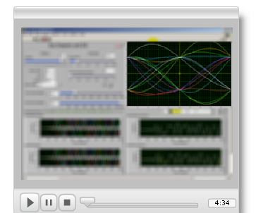
This venture thinks about intersymbol impedance in an instinctive manner by utilizing a LabVIEW VI to recreate a heartbeat transmitter, limited data transmission channel, and got flagging waveform. Rectangular pulse are viewed as first to exhibit the ISI issue, and afterward two elective heartbeat shapes are investigated as an approach to limit ISI.
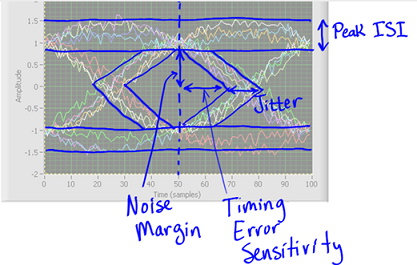
The eye graph is likewise presented in this task as a visual guide to display the time-area flagging waveform to advance comprehension of the ISI marvel. The eye chart additionally uncovers other key execution estimates, for example, clamor edge, timing jitter, and timing affectability.
Rectangular Pulse
Reestablish the front board controls of diagram to their default esteems, and set the images control to 40. Shift the channel data transmission and watch its impact on the eye graph plot, and after that set the channel transfer speed to 0.05. Increment the eye chart start time to 245 examples to focus the eye in the plot window.
ORDER NEW COPY OF SAMPLING RATE AND DIGITAL PROCESSING ASSIGNMENT & GET HIGH QUALITY SOLUTIONS FROM SUBJECT'S TUTORS!
Fare the eye outline plot to a bit of paper, and afterward utilize the eye chart cursor as an instrument to gauge the accompanying (show and mark the applicable separations you quantified on your printed version plot):
Ideal inspecting time; report this as the quantity of tests from the closest zero intersection
Pinnacle ISI
Zero intersection jitter; report this as the most extreme variety in time tests
Commotion edge
Raised Cosine Pulse
Keep the front board controls of diagram at similar settings you utilized for the past "Sinc" beat estimations, and after that select the "Raised Cosine" beat shape. You ought to hope to see the most extreme enlightening stay focused in the eye outline plot.
As in the past advances, trade the eye chart plot to a bit of paper, and afterward utilize the eye outline cursor as a device to quantify the indistinguishable five measurements from for the "Sinc" beat. Show and mark the important separations you gauged on your printed copy plot.
Think about your outcomes for the raised cosine beat and the sinc beat. What has all the earmarks of being profitable about the raised cosine heartbeat shape?
Eye Diagram
Q4. Using root-raised-cosine pulses and receiver filtering, observe the eye diagram when the input of MT Format Eye Diagram is set to "baseband output" and when the input of MT Format Eye Diagram is set to the "aligned waveform" output of PulseAlign(real). What function is PulseAlign(real) performing?
The seed front-board control in the "Beats" segment prepares number generator that makes the message bitstream. Don't hesitate to attempt other seed esteems to create other piece groupings for the message. this outline utilizes two programming strategies that you may wish to explore further, to be specific, an occasion structure and property hubs. Type Ctrl+E to demonstrate the square outline window, and watch the occasion structure inside the while-circle structure. The occasion structure possibly "fires" when a front-board control worth changes; the CPU doesn't do any work but to in a flash react to front-board movement. The occasion structure makes the VI receptive to client input, yet doesn't trouble the CPU as would a plain while-circle.
The property hubs permit front board controls and pointers to be automatically controlled. For instance, changing the estimation of the examples front-board control makes the furthest reaches of beginning time naturally change to a similar worth.
SAVE TOP GRADE USING SAMPLING RATE AND DIGITAL PROCESSING ASSIGNMENT HELP SERVICE OF EXPERTSMINDS.COM!
Q5. The transmitter is programmed to generate the same "frame" of 1000 symbols over and over. The receiver grabs a single block of 2000 symbols each time it is run. Can you identify, by examining the receiver's baseband output plot, where the symbol sequence ends and starts over? Frame synchronization of the receiver is an essential component of a digital communication system. We will examine frame synchronization in the next part of this lab project.
According to the plot which is generated as
The plot contains seven follows:
Separated Baseband: This follow is the fundamental simple sign leaving the restricting speakers.
RC Threshold: This follow is a decreased plentifulness, stage postponed adaptation of the sifted baseband signal.
Max Peak w/Decay: This follow utilizes a selectable tau incentive to speak to an intermittently topping sign.
Min Peak w/Growth: Similar to the maximum pinnacle, this follow utilizes a similar tau to speak to an intermittently diving signal.
Picked Threshold: This follow utilizes the RC limit as its source, or a normal of the Max Peak and the RC Edge, or a normal of the maximum pinnacle and min pinnacle signals.
Information Output (RC Threshold): This spotted line follow demonstrates the information yield if just the RC slicer level is utilized to create the limit level.
Picked Data Output: This follow looks at the separated baseband to the picked limit to create the yield Client sources of info are required in a couple of cells to help group the plot and to speak to certain decisions in the structure. Baseband counterbalance is just a balanced degree of the sifted baseband signal as exhibited in the plot. Introductory limit balance and last edge balance give two conditions to the client to change the dataslicing edge end focuses. These passages are shown by a blue shading. Information balance can be utilized to modify the area of the computerized information follow. This section is featured in green. Pinnacle identifiers enable the client to pick the various setups associated with the cutting limit. Taking note of a "0" demonstrates that no pinnacle identifier follows are utilized to decide the limit; "P" will average the RC edge with the maximum (positive) top identifier; and "B" will average both the most extreme (positive) and least (negative) top identifiers together to create the cutting level. Pinnacle distinguish gives change in accordance with the pinnacle identifier levels Commotion gives a change to incorporate arbitrary clamor esteems on the separated baseband follow, the pinnacle finders, and the RC limit. The amplitudes for each clamor sign can be balanced with the separate cells.
DO YOU WANT TO EXCEL IN SAMPLING RATE AND DIGITAL PROCESSING ASSIGNMENT - ORDER AT EXPERTSMINDS!
Q6 The FM receiver uses a differentiator to undo the integral in Eq. (4). What is the effect of the differentiator on any noise that might be present along with the signal? To answer this, consider what a differentiator does in the frequency domain. What would be the effect of omitting the filter that follows the differentiator?
At higher frequencies the reactance of the capacitor is much lower bringing about a higher addition and higher yield voltage from the differentiator speaker. In any case, at high frequencies an operation amp differentiator circuit winds up unsteady and will begin to waver. This is expected essentially to the main request impact, which decides the recurrence reaction of the operation amp circuit causing a second-request reaction which, at high frequencies gives a yield voltage far higher than what might be normal. To maintain a strategic distance from this the high recurrence increase of the circuit should be decreased by including an extra little esteem capacitor over the input resistor Rƒ. Alright, some math's to clarify what's happening!. Since the hub voltage of the operational intensifier at its upsetting info terminal is zero, the current, I moving through the capacitor will be given as: operation amp gain condition.
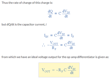
Therefore, the yield voltage Vout is a steady - Rƒ*C times the subordinate of the information voltage Vin as for time. The less sign demonstrates a 190 stage move on the grounds that the information sign is associated with the rearranging input terminal of the operational speaker.
One last point to make reference to, the Op-amp Differentiator circuit in its essential structure has two principle burdens contrasted with the past operational intensifier integrator circuit. One is that it experiences insecurity at high frequencies as referenced above, and the other is that the capacitive info makes it truly powerless to arbitrary commotion signals and any clamor or sounds present in the source circuit will be intensified more than the information signal itself. This is on the grounds that the yield is relative to the slant of the info voltage so a few methods for constraining the data transfer capacity so as to accomplish shut circle dependability is required
Part B -
Q1. With the peak frequency deviation set at 5000 Hz, compare the rate of spectral rolloff with rectangular pulses and with Gaussian filtering. Also, by examining the plot of the transmitted message signal, can you find evidence of intersymbol interference when Gaussian filtering is used?
A rectangular heartbeat with gaussian sifting and with sudden advances is a characteristic decision for killing ISI. In the event that a data arrangement is molded as rectangular heartbeats, at the image examining moments, the obstruction because of different images are constantly zero. Simpler to execute in equipment or programming, a rectangular heartbeat p(t) of term Tsym can be produced by the accompanying capacity
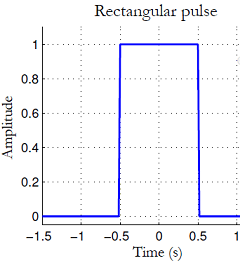
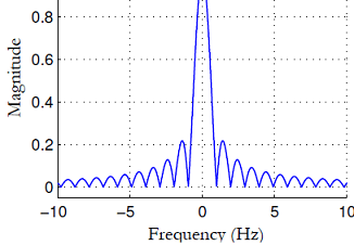
As appeared in Figure the rectangular heartbeat in the time-area shows as a sinc work that broadens unendingly on either side of the recurrence range (however just a bit of the recurrence reaction is plotted in the figure) and along these lines its range isn't band-constrained. At the point when the limitlessly broadening recurrence reaction is full inside a band-constrained channel, the truncation of the range prompts vitality spills in the time-area. If we somehow managed to utilize sharp rectangular heartbeats, it needs an immense data transfer capacity that could damage useful structure specs.
DON'T MISS YOUR CHANCE TO EXCEL IN SAMPLING RATE AND DIGITAL PROCESSING ASSIGNMENT! HIRE TUTOR OF EXPERTSMINDS.COM FOR PERFECTLY WRITTEN SAMPLING RATE AND DIGITAL PROCESSING ASSIGNMENT SOLUTIONS!
Q2. For each value of peak frequency deviation listed in Step 5, compare the null-to- null bandwidth of the transmitted signal with the bandwidth predicted by Carson's rule, Eq. (1). Compute the percentage difference in each case. Is Carson's rule more accurate for large peak frequency deviation or for small peak frequency deviation?
We consider the data transmission of a Frequency Modulated (FM) bearer when it is tweaked by a 1 KHz sinewave. The adjustment record for FM is characterized to be:
b =DFpk/(Fm)
Where DFpk is the pinnacle recurrence deviation of the transporter recurrence, and Fm is the recurrence of the adjusting sinewave. The abundancy of the unearthly segments of the tweaked sign are controlled by Bessel capacities.
J0(b) is the bearer adequacy
J1(b) is the adequacy of the balancing recurrence sidebands, Fc +/ - Fm
J2(b) is the adequacy of the sidebands at Fc +/ - 2Fm
The occupied bandwidth for 98% of the transmitted power is determined from Carson's Rule
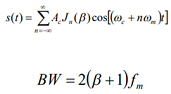
The data transfer capacity of a sign gives a proportion of the degree of huge otherworldly substance of the signal for positive frequencies. At the point when the sign is carefully band restricted the transmission capacity is well characterized. Be that as it may, the importance of "noteworthy" is scientifically loose when the sign is not carefully band restricted. A few designing meanings of data transfer capacity are generally being used, counting: Invalid to-invalid data transmission: scope of frequencies between zeros in the size range.
Q3. Observe the eye diagram shown on the receiver front panel. Compare the display when the eye diagram shows the baseband output waveform and when the eye diagram shows the aligned baseband output waveform. Describe what function PulseAlign(real) is performing.
Eye graph examination yields great measures of data. Eye outline examination is important in configuration, troubleshooting, and support. As the recurrence rises, new issues rise. Transmission line marvels must be comprehended and stood up to, particularly in regards to impedance coordinating. Slight assembling and establishment blunders corrupt trademark impedance, and the subsequent information reflections and impacts increment the level of mistake. Indeed, even slight PCB follow misdesign or development blunder can cut down a whole arrange. The most feasible strategy for distinguishing and finding such blames is by contrasting previously, then after the fact (concerning the information stream) eye outlines.
The top bar in an eye chart is the consequence of discrete high rationale expresses that agree vertically however not evenly. Covering low rationale states make the ceaseless base bar. Those pervasive Xs that are a well-known element of eye outlines are because of rising and falling edges that are superimposed at customary interims.
Rapid advanced transmission is portrayed by the presentation into the sign of jitter. It is not out of the ordinary that an electronic sign will be occasional partly. Jitter is the deviation from this periodicity and all things considered it is unsafe as far as sign loyalty
A higher piece rate consistently means a vertically littler educational. Simultaneously, timing mistake as showed in jitter contains a bigger division of the waveform, so we may search for more information blunders
WORK TOGETHER WITH EXPERTSMIND'S TUTOR TO ACHIEVE SUCCESS IN SAMPLING RATE AND DIGITAL PROCESSING ASSIGNMENT!
Q4. Make a plot of the amplitude of the receiver's baseband output waveform vs. the peak frequency deviation. What is the relationship between these two quantities?
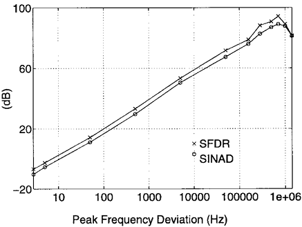
They are directly proportional to each other.
Q5. As described in Lab 7: Amplitude-Shift Keying, one of the quantities easily seen on the eye diagram is the optimum decision threshold location. In the present lab project, you were instructed to set the decision threshold to zero. Run the transmitter and receiver several times for different values of peak frequency deviation and for filtering set to "none" and "Gaussian." Observe the eye diagram and comment on the appropriateness of using zero for the decision threshold.
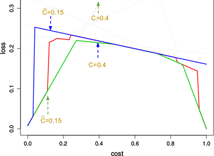
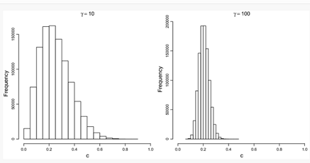
We break down how expected misfortune and cost bends change for expanding vulnerability to the instance of complete vulnerability ( γ=0 ). We locate that numerous limit decision techniques breakdown and become comparable to their uniform partners (e.g., score-driven progresses toward becoming score-uniform) and we can scientifically infer the cost bends and anticipated misfortunes in this outrageous circumstance of complete vulnerability. This enables us to outline the advancement from impeccable working condition data to add up to nonattendance of data for all edge decision techniques, where case C in Table 1 turns into a speculation of the two cases B and D.
Past the ideal estimation of the noise, as per presence of mind, the exhibition of the (2, 2) DMC falls apart what's more, the expansion of clamor winds up disadvantageous. In any case, as the choice edge moves far away from the sign abundancy with approach a lot for the locator to settle on the gotten signal that is a lot littler than our edge. Hence we find the commotion improved impact if there should be an occurrence of the threshold happens in the interim for which the edge worth is somewhat more noteworthy than the sign sufficiency.
EXPERTSMINDS.COM ACCEPTS INSTANT AND SHORT DEADLINES ORDER FOR SAMPLING RATE AND DIGITAL PROCESSING ASSIGNMENT - ORDER TODAY FOR EXCELLENCE!