NEVER LOSE YOUR CHANCE TO EXCEL IN LOCAL AREA NETWORK DESIGN AND SETUP ASSIGNMENT - HIRE BEST QUALITY TUTOR FOR ASSIGNMENT HELP!
MN621 Advanced Network Design - Melbourne Institute Of Technology
Local Area Network Design and Setup Assignment
Question: Plan a network design and setup LAN appropriately using physical networking devices. After successful completion of this assignment, students should be able to:
a. Investigate suitable network designs to match requirements.
b. Create appropriate frameworks and standards for network implementation
A case study: Local Area Network design and configuration
Analyse the need for the network for above case study. Investigate and propose a suitable complete network design for the case study.
Create an appropriate framework and standards for the planned network. Write a detailed setup of network devices only for a LAN.
SAVE TOP GRADE USING LOCAL AREA NETWORK DESIGN AND SETUP ASSIGNMENT HELP SERVICE OF EXPERTSMINDS.COM
Answer:
1. Introduction
The local area network design is executing by a network plan is an iterative process. The network design is analyzing by the telecommunication business. It's aimed at ensuring that a new service meets the wants of the subscriber and operator.
Itgenerate proper standards and frameworks for the planning network. The network devices are using only for LAN was the hierarchical design model to break the design up into modular groups and layers [5]. Include, specified execute report of every networking device.Reveal and differentiating configuration result and also include two PCs, routers switches on the physical networking devices.
2. Project Scope
The network design has to be done within time and budget. The customer's necessity and the protection must be satisfied with the network designed.
The approaching speed and security of the network are increased using the latest technology for designing a network [9].
3. Hardware requirements
The LAN network design used in hardware are routers, cables, switches, computers, and servers.
Switch:
The device that conducts the TCP/IP from source to destination uses the port for transferring is called Switch. The computers,cameras, phones, lights, and printers are connected using Switches [10].
Advantages:
• Lower cost
• Switches are easy to deal with and functional
• Provides Quality of Service (QoS) to VoIP and applications to business
• Features in switch give more security
Router:
Route manipulates the routing table for routing the packets or data sent by theis considered or calculated.
The packets are received by the router from the computer. The packets are analyzed and the packets are taken over the required network.
|
|
Series
|
Model
|
Cost
|
|
Switch
|
Cisco Catalyst 2960S-24PS-L 24 Port Switch
|
Catalyst 2960S-24PS-L
|
$ 644 for each switch
|
|
Router
|
Cisco 890 Series
|
C891F-K9
|
$401
|
Cables:
One of the network cable used is Ethernet cable. The signals on the internet are transferred through the wire [4].
LAN connections are used to connect the printers, servers, Routers, Switches, PC in the network. The commonly used Ethernet cables are Category 5 cables and Category 6 cables. The weakness of the occurs when distraction occurs on the cable. Ethernet usesa distinct type of cable called crossover cable. The connec5tion is between two different computers. The cable costs Rs.300.
Server:
The Local Area Network design uses Dell T430 Xeon E5-2609V4 model as a server. The reduction in the technical error and decreased operation time is possible. The server cost is 2086$.
Computers:
Network design is based on the computer. Ground floor used 11 computers.first floor used 50 computers and second floor used 38 computers. totally 99 computers are used. The identification for every computer is given below
• Operating System: Windows 10
• RAM Memory: 4 GB
• Size: 17" inches
• Hard - disk space: 20 GB
• Graphics card: DirectX 9
• Cost: $430
Some hardware is used in LAN network design. Three floors are used based on computers. Eleven nodes are used on the ground floor.Especially nodes are used as computers. In the ground floor, Cisco switches, and Cisco routers are used in the network devices. The imitation of the Cisco switch is catalyst 2960S-24PS-L. The first floor having 24 ports [2]. They wanted three rooms. Three rooms are needed on the ground floor. They are the warehouse, reception, and foyer.
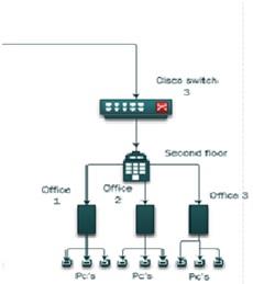
The first floor requires five offices. In every office, forty cubicles are there. They want only ninety nodes. The first floor wants one switch. Interrelationships are used in the core switch and routers in the computer. In network design, standard Cisco devices are used. On the third floor, they want two offices and thirty cubicles. Here they require two hundred and sixteen computers for the local area network design. They distribute study in the based on computer.and also every floor want the wireless network [11]. They need one access point for wireless access. In the second and third floor, they want the wireless device and access point.
Write a detailed implementation report which includes configurations of each networking device which are included in the whole network.
4. Network design
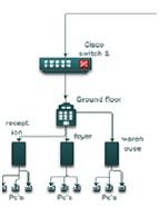
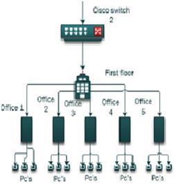
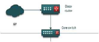
According to the case study, the network design is described by the Visio software. And it also needs certain of the hardware. The local area network wants computer nodes, offices, rooms on each floor. Some network devices are used for the connectivity in each floor such as user, router, servers and it also used for the configuration. Cisco standard is used as the model in these devices. It contains three Cisco switches, one core switch and one Cisco router. It utilizes three floors which are named as the ground floor, first floor, second floor. Internet service provider gives the internet connection it is named as the main network. For passing the network router is used as the pathway. The ground floor is placed with the warehouse, foyer, and reception and it totally contains 11 pcs and for the designing it uses nine pcs. And i9n the first floor there are five offices according to the mode of study and it contains fifteen pcs [1].
The second floor with the nine pcs and with the three offices. Each floor contains local area network connectivity and it also delivers interconnection for the needed floor. Here switches and routers are used as the network devices.
SAVE YOUR HIGHER GRADE WITH ACQUIRING LOCAL AREA NETWORK DESIGN AND SETUP ASSIGNMENT HELP & QUALITY HOMEWORK WRITING SERVICES OF EXPERTSMINDS.COM
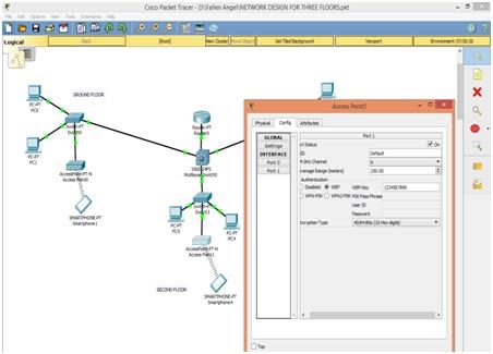
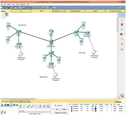
5. Network Design of Three floors
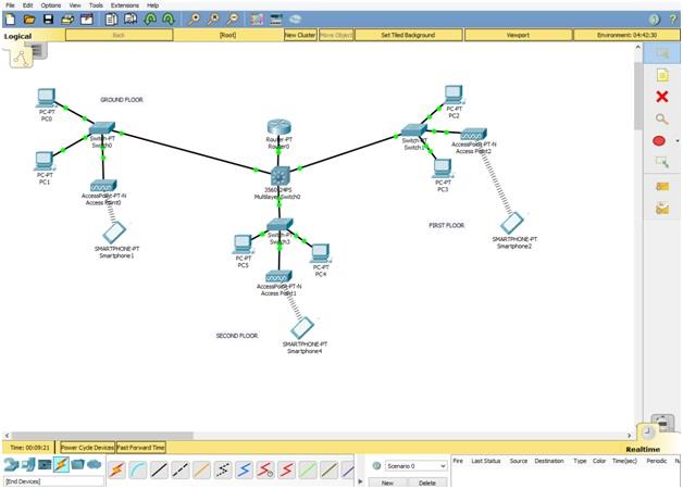
Cisco packet tracer is used to produce a network. The clarity among the software in network design are in less amount are moved. In this software, one multilayer switch, one Cisco router, and three switches. The basement has two nodes, one switch and holds wireless access point. Among the first floor, two nodes are to be connected to the switch and it is connected with the wire3les access. The second floor, the two sides are allied with 24 port switch and also with access [point. in that floor, the three wireless switches are associated with the Core switch and access point are oriented for smartphones among the core switch. The connection is created among the design. For each network, the IP address is assigned and it must be used in 192.168.30.0 and it belongs to the class of C [6]. the Single subnet are seized for designing for LAN network and the host bits are available is seven, so the number of hosts is applicable is126(2^7=128 and then 128-2=126, now the host IP address are accessible). Default subnet screen of the network is 255.255.255.0 and it is changed. Among the two subnets contains totally ninety-nine nodes are plotted. Two nodes are needed in the ground floor and their IP addresses are 192.168.30.2 and 192.168.30.3. The bikes are present on the second floor and their IP addresses are 192.168.30.6 ad192.168.30.7. And the only one single router is used in the Designing of LAN Network and its routers are 192.168.30.1. The three smartphones are fixed for wireless access. Corresponding smartphones are 192.168.360.20, 192.168.30.1 and 192.168.30.30. IT provider's wireless connections among the wireless connections in the reach floors and these are connected to the switch and these three access points are secured keys for the wireless connection over the switches [3].
DONT MISS YOUR CHANCE TO EXCEL IN LOCAL AREA NETWORK DESIGN AND SETUP ASSIGNMENT! HIRE TUTOR OF EXPERTSMINDS.COM FOR PERFECTLY WRITTEN LOCAL AREA NETWORK DESIGN AND SETUP ASSIGNMENT SOLUTIONS!
Demonstrate and compare at least 2 configuration results which may include at least two switches/routers and two PCs on physical networking devices.
6. Configuration of Network devices step-by-step
Step 1: Configuring IP address
IP address Configuration of PC0
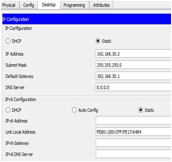
Click the "Desktop" in the PC0. And then press "IP Configuration" Now we can able to see the IP configuration wizard. In IP configuration wizard enter the IP address as "192.168.30.2".
IP address Configuration of PC1
Click the "Desktop" in the PC1. And then press "IP Configuration" Now we can able to see the IP configuration wizard. In IP configuration wizard enter the IP address as "192.168.30.3".

IP address Configuration of PC2
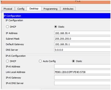
Click the "Desktop" in the PC2. And then press "IP Configuration" Now we can able to see the IP configuration wizard. In IP configuration wizard enter the IP address as "192.168.30.4".
IP address Configuration of PC3
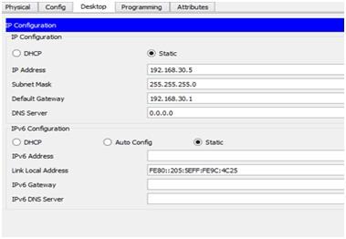
Click the "Desktop" in the PC3. And then press "IP Configuration" Now we can able to see the IP configuration wizard. In IP configuration wizard enter the IP address as "192.168.30.5".
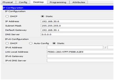
IP address Configuration of PC4
Click the "Desktop" in the PC4. And then press "IP Configuration" Now we can able to see the IP configuration wizard. In IP configuration wizard enter the IP address as "192.168.30.6".
WORK TOGETHER WITH EXPERTSMIND'S TUTOR TO ACHIEVE SUCCESS IN LOCAL AREA NETWORK DESIGN AND SETUP ASSIGNMENT!
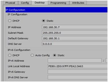
IP address Configuration of PC5
Click the "Desktop" in the PC5. And then press "IP Configuration" Now we can able to see the IP configuration wizard. In IP configuration wizard enter the IP address as "192.168.30.7".
Step 2: IP configuration of Router
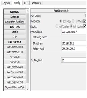
In this stage, the IP address for the router has been assigned. The IP address for the router is assigned using FastEthernet 0/0 interface. It is there under the "config" tab. After opening the FastEthernet 0/0 interface enter the IP address as "192.168.30.1".
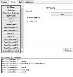
In the same "Config" tab we can see the "RIP". Select the RIP tap. Now it shows the "RIP Routing" table. Now we have to enter the IP value as "192.168.30.0".
Step 3: Default Gateway Address configuration
Default gateway Address configuration for PC0
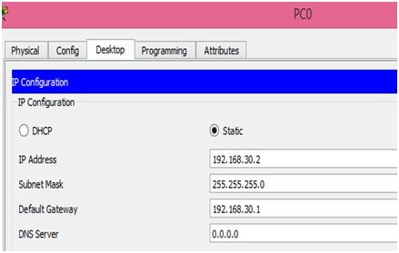
In this stage, we have to enter the default gateway value for the PC0. This process is carried out after the IP address for the PC0 is configured. Here the default gateway value is "192.168.30.1". It is shown in the above attached figure.
Default gateway Address configuration for PC1
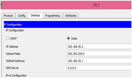
In this stage, we have to enter the default gateway value for the PC1. This process is carried out after the IP address for the PC1 is configured. Here the default gateway value is "192.168.30.1". It is shown in the above attached figure.
Default gateway Address configuration for PC2
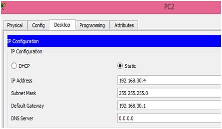
In this stage, we have to enter the default gateway value for the PC2. This process is carried out after the IP address for the PC2 is configured. Here the default gateway value is "192.168.30.1". It is shown in the above attached figure.
Default gateway Address configuration for PC3
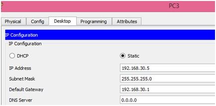
In this stage, we have to enter the default gateway value for the PC3. This process is carried out after the IP address for the PC3 is configured. Here the default gateway value is "192.168.30.1". It is shown in the above attached figure.
Default gateway Address configuration for PC4
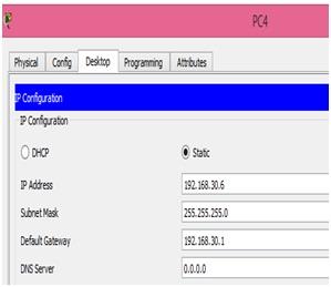
In this stage, we have to enter the default gateway value for the PC4. This process is carried out after the IP address for the PC4 is configured. Here the default gateway value is "192.168.30.1". It is shown in the above attached figure.
Default gateway Address configuration for PC5
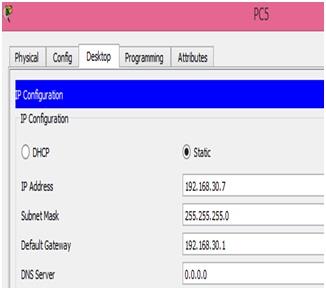
In this stage, we have to enter the default gateway value for the PC5. This process is carried out after the IP address for the PC5 is configured. Here the default gateway value is "192.168.30.1". It is shown in the above attached figure.
ARE YOU LOOKING FOR RELIABLE LOCAL AREA NETWORK DESIGN AND SETUP ASSIGNMENT HELP SERVICES? EXPERTSMINDS.COM IS RIGHT CHOICE AS YOUR STUDY PARTNER!
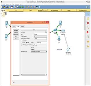
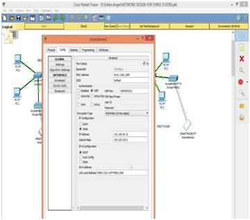
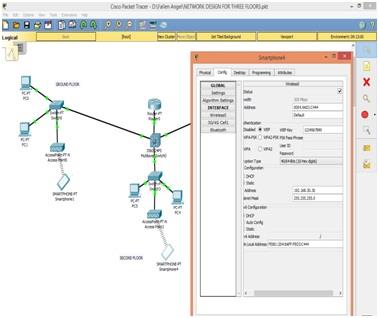
Step 4: Configuration of Access Point0, Access Point1 and Access Point2 in the Network Design
Configuration of access Point 0
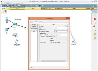
"Config" tab has a "Port 1" option. Press the "Port 1" option. Now we can see the access point configuring wizard. In the access point configuring wizard, we need to select the "WEP" in Authentication option and enter the WEP key as 0246813579.
Configuration of access Point 1
"Config" tab has a "Port 1" option. Press the "Port 1" option. Now we can see the access point configuring wizard. In the access point configuring wizard, we need to select the "WEP" in Authentication option and enter the WEP key as 1234567890.
Configuration of access Point 2
"Config" tab has a "Port 1" option. Press the "Port 1" option. Now we can see the access point configuring wizard. In the access point configuring wizard, we need to select the "WEP" in Authentication option and enter the WEP key as 0987654321.
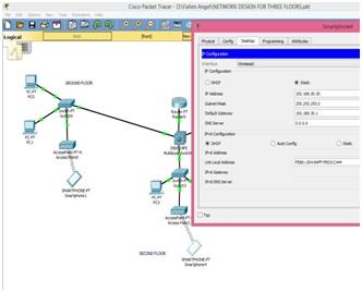
Step 5: IP Configuration and wireless configuration of Smartphone0, Smartphone1 and Smartphone4 in the Network Design
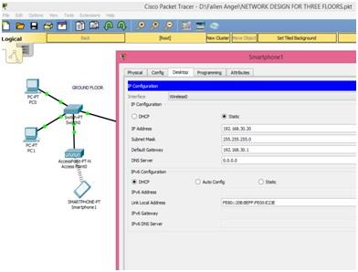
For smartphone 1 IP address and default gateway is assigned in this stage. IP address for the smartphone1 is "192.168.30.20" and the default gateway value as "192.168.30.1".
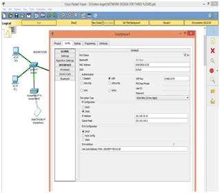
Access Point0 is connected with Smartphone1 to select WEP and on Access Point0 enter the WEP key 0246813579. The Access Point0 is connected to Smartphone1 after entering this key.
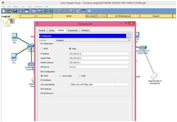
The default gateway and the IP address is entered for Smartphone2. Smartphone1 uses IP address entered is 192.168.30.10 and default gateway is 192.168.30.1
Access Point1 is connected with Smartphone2 to select WEP and on Access Point1 enter the WEP key. Access Point1 uses 1234567890 WEP Key. The SmartPhone2 is connected to AccessPoint1 after the key is entered.
The default gateway and IP address is entered. The IP address is of Smartphone is 192.168.30.30 and default gateway is 192.168.30.1
The Access Point2 connected with Smartphone4 to select WEP and to enter the WEP key.Access Point0 uses 0987654321 WEP key. The Smartphone4 is connected to Access point2 after the key is entered.
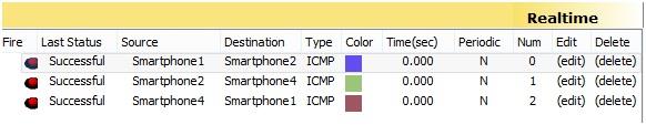
The right corner area of the bottom has list of status of every single transmission of data from source to destination on PC.
DO YOU WANT TO EXCEL IN LOCAL AREA NETWORK DESIGN AND SETUP ASSIGNMENT? HIRE TRUSTED TUTORS FROM EXPERTSMINDS AND ACHIEVE SUCCESS!
7. Results of Configuration
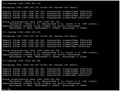
To check the network connection in the Cisco packet tracer software, simple PDU and ping commandis used. To configure the source and destination computers network cisco packet tracer is used as the command prompt which is in the ping command. In Cisco packet tracer, simple PDU is used as the closed envelope. Click on the envelope box their opens the source system and destination system and it shows the 'successful' in the packet box when they are in their connectivity. Or else it displays 'Failed'. The results of the configuration are shown by the ping command and simple PDU in the below-given table [8].
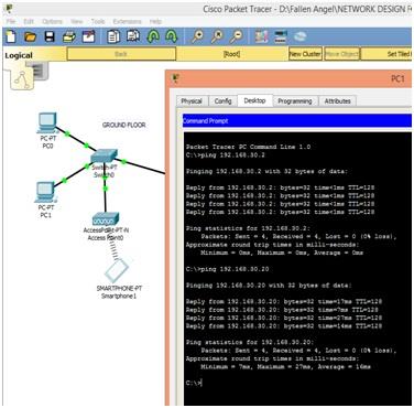
The ground floor with the PCO, PC1 and smartphone1 in the screenshot which shows that PC1 is ping with PCO and smartphone1
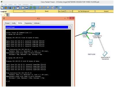
The first floor which contains PC2, PC3 and smartphone2 in the screenshot that shows PC3 is ping with PC2 and smartphone2
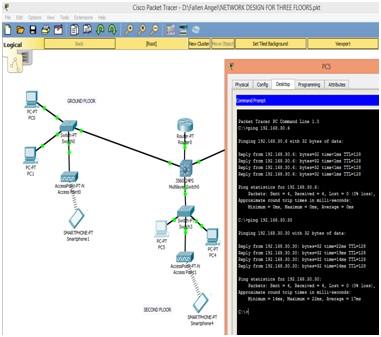
This screenshot describes the connection with PC5, PC4 and Smartphone4. Second floor has PC4, PC5 and Smartphone4
This screenshot describes the connection with PC0 and PC1 and with PC3 and PC5 (on Second floor) on the different floor rather on PC1 is on same floor (on Ground floor)[12].
User-created packet box is illustrated in the above-given figure. From that, we can able to know about the information related to data transmission from data resources to the destination.
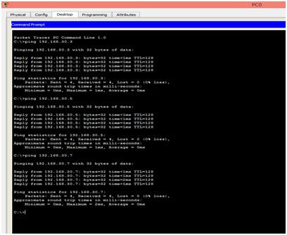
The above-given figure shows the connection between the PC0 and smartphone. Both are connected to the same network but located on different floors.
8. Conclusion
By using the study requirement we created network designing which is based on LAN network. Network designing is done with the help of hardware elements. The elements which are namely computer, switches, cables and routers. It clearly describes their cost and specifications. With the help of Visio software we created network diagram and describing in detailed. We provide thorough explanation for network designing[7].Cisco packet tracer program which is used for network diagram. In network diagram, we provide IP allocation statement and specifications. Computers and routers are shown in the diagram. We express the organization conclusion and explained in the screenshots.
EXPERTSMINDS.COM ACCEPTS INSTANT AND SHORT DEADLINES ORDER FOR LOCAL AREA NETWORK DESIGN AND SETUP ASSIGNMENT - ORDER TODAY FOR EXCELLENCE!
Below are the related courses in which we offer Assignment Help Service:
- MN621 Advanced network Design Assignment Help
- MN506 System Management Assignment Help
- MN501 Network Management in Organisations Assignment Help
- MN691 Research Methods and Project Design Assignment Help
- MN502 Overview of Network Security Assignment Help
- MN692 Capstone Project Assignment Help
- MN504 Networked Application Management Assignment Help
- MN601 Network Project Management Assignment Help
- MN503 Overview of Internetworking Assignment Help
- MN603 Wireless Networks and Security Assignment Help