ARE YOU LOOKING FOR RELIABLE SENDING END VOLTAGE AND LOAD ANGLE ASSIGNMENT HELP SERVICES? EXPERTSMINDS.COM IS RIGHT CHOICE AS YOUR STUDY PARTNER!
Question 1 - (a) A short 3-phase 11 kV line delivers a load of 4.1 MW, 2.6 MVAr lag. If the series impedance of the line is (72 + j12.1)Ω/ph, calculate the sending end voltage and load angle.
Answer - Take the reference voltage as
VR = (33<0)/√3 = 19.07 < 0 KV/ph
Now power = √3 VLIL Cos∅
Power = 4.1MW
IL = Power/(√3 VL cos∅)
From the power triangle tan θ = MVAR/MW
Tanθ = 2.6/4.1
θ = tan-1 2.6/4.1 = 32.8o
So cos ∅ = 0.84
VL = 11kv ×3 = 33×103 V
Substituting these values
IL = (4.1×10⁶)/(√3×33×103×0.84) = 85.39 < cos-1 0.84
= 71.78 - j46.26
Now IZ= (71.78 -j46.26) × (7.2+j12.1)
= 1076.562+j535.466
VS = VR+IZ
=19.07×10³ < 0 + 1076.562+j535.466
= 20146.562+j 535.466
= 20154 V/ph
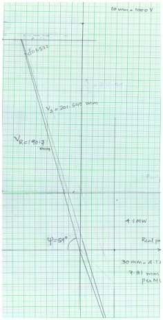
And δ = 1.522
SAVE YOUR HIGHER GRADE WITH ACQUIRING SENDING END VOLTAGE AND LOAD ANGLE ASSIGNMENT HELP & QUALITY HOMEWORK WRITING SERVICES OF EXPERTSMINDS.COM!
(b) Develop the receiving end performance chart for the above line and load to a 3-phase power scale.
Answer - Graphical plot
As we know VR = 19.07KV/ph
Here it is given that 10mm = 1000V
So 19.07KV = (19.07KV×10mm)/1000V = 190.7mm
Similarly VS = 20154V/ph
Here it is given that 10mm = 1000V
So 19064 = (20154×10mm)/1000V = 201.540mm
Here 7.2+j12.1 = 1.08 +j59.25
So φ = 59.25
Question 2 - Using the chart you produced in Question 1, determine: (a) the real and reactive power when
(i) The transmission angle remains unaltered and the sending end voltage is increased by 28%.
Answer - When Vs is increased by 28%
201.540mm is extended by 28%
(28×201.50)/100= 56.43mm
MW becomes =
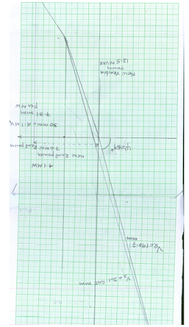
30mm = 4.1MW
26 mm = (26 ×4.1)/30 = 3.5MW
Real Power becomes = 4.1 +3.5 = 7.6MW
MVAR becomes = 12.5 M VAR
DO YOU WANT TO EXCEL IN SENDING END VOLTAGE AND LOAD ANGLE ASSIGNMENT? HIRE TRUSTED TUTORS FROM EXPERTSMINDS AND ACHIEVE SUCCESS!
(ii) The original sending-end voltage is reduced by 15% and the transmission angle increased by 9o.
Answer - When Vs is reduced by 15%
Then VS will be 201.540 × 0.85 = 171.309 mm
MW becomes =
30 mm = 4.1 MW
15mm = (15 ×4.1)/30 =2.05MW
MVAR becomes = 3.5 M VAR
δ = 1.522 +9 = 9.522
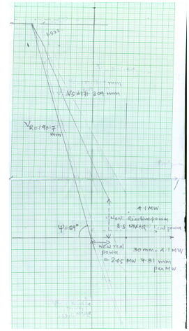
(b) The real power limit for the sending voltage in (ii) above (i.e. when reduced by 15%).
Answer - When an arc is drawn the maximum limit will be 20MW.
EXPERTSMINDS.COM ACCEPTS INSTANT AND SHORT DEADLINES ORDER FOR SENDING END VOLTAGE AND LOAD ANGLE ASSIGNMENT - ORDER TODAY FOR EXCELLENCE!