24/7 AVAILABILITY OF TRUSTED BASEBAND POWER SPECTRUM ASSIGNMENT WRITERS! ORDER ASSIGNMENTS FOR BETTER RESULTS!
Question 1. On the Diagram of the receiver program, write the name of each node (sometimes calledfunction or block) and its purpose on the block diagram. (Such as niUSRP Open Rx Sessioncreates a session handle to the device for other functions).
Solution:
AT receivers end
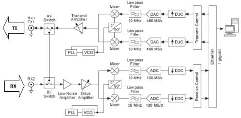
Get Path:
Either a low-commotion speaker (LNA) or a LNA low-pass channel (LPF) blend intensifies the approaching sign, contingent upon the approaching recurrence.
The sign goes through either an immediate change way or an up transformation way, contingent upon the recurrence.
A last driver enhancer enhances the sign.
The stage bolted circle (PLL) controls the voltage-controlled oscillator (VCO) so the gadget tickers and nearby oscillator (LO) can be recurrence bolted to a reference signal.
The blender in the 10 MHz - 500 MHz way upconverts sign to 2.44 GHz.
The bandpass channels points of confinement flag in the 10 MHz - 500 MHz recurrence range to 84 MHz of data transfer capacity.
The quadrature blendersdownconvert the sign to the baseband in-stage (I) and quadrature-stage (Q) segments.
The lowpass channel lessens clamor and high recurrence parts in the sign.
The simple to-computerized converter (ADC) digitizes the I and Q information.
The computerized downconverter (DDC) blends, channels, and destroys the sign to a client determined rate.
The downconverted tests are passed to the host PC over a standard PCIe association.
MOST RELIABLE AND TRUSTWORTHY BASEBAND POWER SPECTRUM ASSIGNMENT HELP & HOMEWORK WRITING SERVICES AT YOUR DOORSTEPS!
Question 2. On the Diagram of the transmitter program, write the name of each node and its function onthe block diagram. (Such as niUSRP Open Tx Session creates a session handle to the devicefor
Solution:
Transmit Path:
The host PC blends baseband I/Q flag and transmits the sign to the gadget over a standard PCIe association.
The computerized upconverter (DUC) blends, channels, and inserts the sign to 400 MS/s.
The computerized to-simple converter (DAC) changes over the sign to simple.
The lowpass channel diminishes commotion and high recurrence segments in the sign.
The blender upconverts the sign to a client indicated RF recurrence.
The PLL controls the VCO with the goal that the gadget tickers and LO can be recurrence bolted to a reference signal.
The sign goes through either an immediate transformation way or a down change way, contingent upon the recurrence.
The transmit speaker enhances the sign and transmits the sign through the radio wire.
GET READYMADE BASEBAND POWER SPECTRUM ASSIGNMENT SOLUTIONS - 100% PLAGIARISM FREE WORK DOCUMENT AT NOMINAL CHARGES!
Question 3. Describe how you changed the "spike" on the Baseband Power Spectrum graph to 150 KHz.
Solution:
Steps to be taken
1.Associate the TX1 yield to the RX2 SMA connector utilizing a loopback link and 30 dB attenuator gave.
2. Associate the USRP programming characterized radio to the PC as depicted in the Getting Begun Guide5 for your NI USRP handset.
3. Dispatch the NI USRP Configuration Utility6 to discover the Device Name for your NI USRP gadget.
4. From the anteroom in LabVIEW Communications, open the accompanying NI USRP model:
ExamplesHardware Input and OutputNI USRP HostSingleDeviceSingleChannelContinuous→RX Continuous Async
5. Give the model an undertaking name and snap Create.
6. From the model, open another NI USRP model:
File→Examples→Hardware Input and Output→NI USRP Host→SingleDevice→SingleChannel→Continuous→TX Continuous Async
7. Give the model a venture name and snap Create.
8. On the Tx Continuous Aysnc model (alluded to as the transmitter program), enter the gadget name you discovered utilizing the USRP setup utility and note the estimation of the tone recurrence control. This program produces a solitary recurrence tone at baseband and sends it to the USRP.
9. Run the transmitter program.
10. On the Rx Continuous Async model (alluded to as the beneficiary program) model window, enter a similar gadget name as the transmitter and change the Active Antenna to RX2.
11. Run the beneficiary program and break down the Baseband Power Spectrum Graph. You ought to see a spike close to the focal point of the diagram. This is the single tone that was produced by the transmitter
12. Without changing the estimation of the Carrier Frequency control on the collector or transmitter program, "move" the area of the single tone on the Baseband Power Spectrum diagram to 150 kHz.
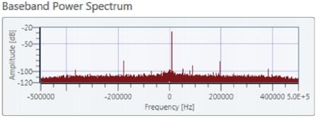
Changed spike Block diagram
GET ASSURED A++ GRADE IN EACH BASEBAND POWER SPECTRUM ASSIGNMENT ORDER - ORDER FOR ORIGINALLY WRITTEN SOLUTIONS!