EXPERTSMINDS.COM GIVES ACCOUNTABILITY OF YOUR TIME AND MONEY - AVAIL TOP RESULTS ORIGINATED ELECTRICAL CIRCUITS AND THEIR APPLICATIONS ASSIGNMENT HELP SERVICES AT BEST RATES!
Electrical Circuits and Their Applications Assignment
Unit 15 Electrical Circuits and their Application - Pearson BTEC Level 3 National Extended Certificate in Applied Science
Learning aim 1: Understand electrical symbols, units, definitions, relationships and properties of circuit components for use in the construction of circuits.
Learning aim 2: Construct series and parallel circuits for use in standard electrical applications and measure electrical values.
Question: State the symbols for the following cell components in a table
24/7 AVAILABILITY OF TRUSTED ELECTRICAL CIRCUITS AND THEIR APPLICATIONS ASSIGNMENT WRITERS! ORDER ASSIGNMENTS FOR BETTER RESULTS!
Section 1: Electrical symbols, units and definitions
Solution:
The Electrical components name and units are listed below
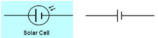
1. Cell
Symbol
Glossary and definitions with units:
• It is a storage of internal energy which can be converted/Transferred as an Electric current when connected in the circuit.
• Cell is a power generating device which converts stored chemical energy to potential electrical energy.
• Allows the flow of current from + terminal (cathode) to - terminal (anode)
• Electrical potential at the +ve end is always high, so there will be high potential /voltage at the cell.
• Since the current flows inside the cell, which results in causing potential energy to be increased. It is denoted by
E = Vq
Where E= Potential energy
V=voltage
q= charge
finally voltage of a cell is energy produced by the cell per unit of charge passing across the junction.
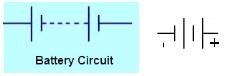
2. Battery
Symbol:
Glossary and definitions with units:
• Battery is formed by connecting the two or more cells in an electrically method.
• These cells could be connected series or parallel to get a circuit closed
• Electrical potential produced in the battery depends on the electrodes, number of cells and type of cells and also connection in series or parallel
• Battery voltages varies from 1.5Volts to 48 Volts (units)
• Typical Battery circuit is shown below
Types of Battery are
1. Primary: it is only for single usage and they are not rechargeable
2. Secondary: It is a rechargeable categories and can be used for multiple purpose eg., Lead acid battery, Li and Nickel cadmium batter
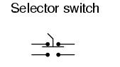
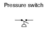
3. Switch
Symbol
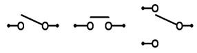
• It is a device that allows the electrons or stops the electrons in the connected circuits.
• Switch has 2 states either Open or Closed
• Number of actual switch position is the key parameters
• No of Poles in the switch
• Number of throws in the switches
• Type of actions at momentary are designed as either NC/NO (Normally Closed or Open)
• Switches are operated by hand, limits based on the levels and process switches operated based on the physical conditions.
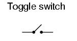
Mostly used in House hold applications and the lever comes on one position after pressing the button
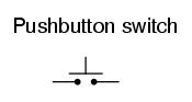
It works when pushed and stays there to be connected and will get released after it is released.
Limit Switch:
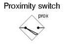
Process Switch:
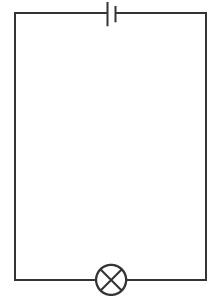
4. Filament Lamp
Symbol
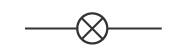
• It is a device with thin coil of wire that generates light sources
• By electrical conductor heated during the current passage in the coil
• It is common light lamp used for testing the electrical circuit whether the circuit is closed or open.
• If the circuit is closed, the lamp will glow. If the circuit is open, then the lamp will not glow
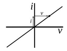
• VI curve of the lamp is shown below
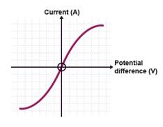
• The lamp resistance increases as the temperature of the coil increases
• The current in the lamp is not related to the voltage across the filament lamp
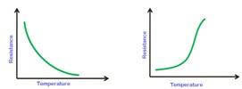
5. Thermistor
Symbol
• This device is used to measure the temperature.
• Rate of change of R-Resistance with T-Temperature
Thermistor= Thermal+ Resistor
• Units with ohms or ohms/degree Celsius
• Relationship between R and T
ΔR = k ΔT
ΔR denotes, resistance changes
ΔT denotes temperature changes
k represents temperature coefficient of resistance of a materials.
• Type of Thermistor
o NTC (Negative temperature co-efficient)
o PTC (Positive temperature co-efficient)
NTC Curve PTC Curve
6. LED (Light Emitting Diode)
Symbol
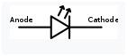
• Anode denotes the positive connection
• Cathode denotes the negative terminal
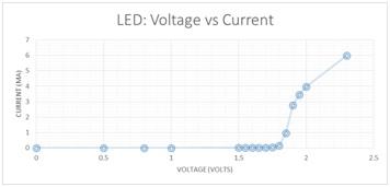
• It is a device that converts the electrical energy flowing the in the connected circuits to a light energy by illumination (visible light or infrared light) when LED is forward biased in the loop by free electrons recombines with holes in the conduction band thus energy is released as a light.
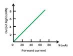
• It is optical semiconductor Diode categories
• Based on the diode we have p type or n-type LED
• Output LED VI curve
7. LDR (Light Dependent Resistor)
Symbol
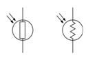
• It is a device used to detect the light source and change the operation based on the circuit closed or open.
• Also called as Photo resistors
• It is semiconductor devices with high resistance
• As the light falls in the devices, this semiconductor device will absorb the light photons, part of the energy is used to reduce the crystal lattice and thus the conduction starts
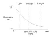
Resistance vs Illumination curve for a LDR
• LDR placed in dark, its resistance is high called as "dark resistance".
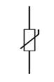
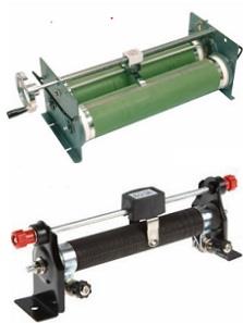
8. Rheostat
Symbol
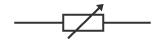
• Rheostat is used to vary the resistance in a circuit.
• It is used to control the I (electrical current) by adding the resistance in the path by manually moving the slider or by any automatically devices
• Unit is Ohms
9. Capacitor
Symbol
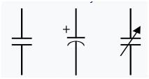
First one: Fixed Capacitor
Second one: Polarised Capacitor
Third one: Variable capacitor
• It is a passive semiconductor device.
• It is used to store the energy in the device by having an electro plates in the design of materials.
• Unit is Farad (F)
• Used for flow control of charge
• It has 2 conducting plates with insulator placed and wires at the end of the devices
• One Farad when charged contains one coulomb of electrical charge with 1 Volt
• Types of Capacitor are 1.Ceramics 2.Electrolytic 3.Film and 4. Variable Capacitor(c)
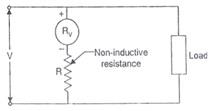
10. Voltmeter
Symbol
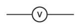
• This is a device used to measure the potential difference between 2 points of circuit
• The output of the device is shown in Volts (v)
• Type of meters are 1. Analog shows the values in Analog scales and 2.Digital voltmeters shows the values in Digital digits
• Voltmeter is connected inparallel to measure the values as the impedance in the circuit is high when connected in parallel. The voltage is same in a parallel circuit as the load in the circuit is same.
• Unit recorded In volts (V)
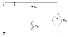
11. Ammeter
Symbol
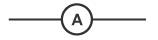
• This device is used to measure the Ampere in the circuit. i.e., current in the circuit
• The output of the device is shown Ampere (A)
• The Ammeter shall have a low resistance and will have low voltage drop and hence this meter shall be connected in series to measure the values as the current in the series circuit is same
• Unit recorded in Ampere (A)
GET ASSURED A++ GRADE IN EACH ELECTRICAL CIRCUITS AND THEIR APPLICATIONS ASSIGNMENT ORDER - ORDER FOR ORIGINALLY WRITTEN SOLUTIONS!
Question: Produce a ‘Glossary of Terms' that defines and gives a brief explanation of each of the following:
Solution:
12. Current
Symbol

• The Ampere is a measure of electrical (e) charge (c) that flow in one second in the connected circuit.
• Unit recorded in Ampere (A)
• 1 A= Charge /sec
• It is shown as I
• Unit of current
13. Potential Difference (volt)
Symbol

• The measure of the potential difference in the electrical circuit
• Unit of Potential difference
• Unit recorded in Volts (V)
• One unit of Volt energy of one Joule consumed when one coulomb of electric charges flow in the connected circuit.
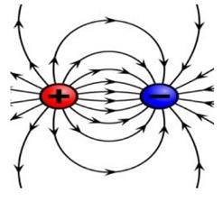
14. Electrical Charge
Symbol

• This unit of electric charge
• Unit recorded of electrical Charge is Coulomb (C)
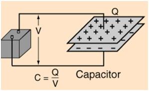
• It is denoted as Q= C*V
• It is physical quantity that produces the force when subjected to Electromagnetic Field.
• Positive and negative charges are produced.
• One Charge=1.602×10⁻¹⁹ coulombs
15. Resistance
Symbol
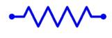
• Unit is of Resistance is measures in Ohms
• It is a Passive electrical component used to resist the electric current flow in the circuit
• It is used to divide the voltage flows
• Also used for bias voltage and termination components
• Represented as R
• One Ampere (I) current flow through one volt potential difference (V) being measured across one value of Resistance.
16. Conductance
Symbol

• Unit is of conductance is measures in Siemens
• It is a reciprocal of resistance
• Electric current flow in a network is measured
• Represented as G=1/R
• Where R is resistance and G is Conductance
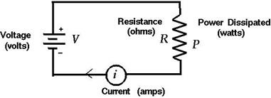
17. Electrical Power
Symbol
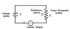
• Unit of Power is Watt(W)
• It is a measure of the Product of W=V*I
• It is represented as P
• Also it could be measured as P=I2*R
• Rate at which energy absorbed or created during the live circuit connection.
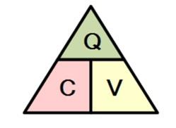
18. Capacitance
Symbol

• Also it could be measured as C=Q/V
• It a nature of a component of electric circuit to store electrical energy
• Unit of Capacitance is Farad (F)
• Sub units are
a. Microfarad
b. Nanofarad
c. Picofarad
d. femtofarad
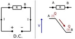
19. Conventional Electric current
Flow of electric charge carriers in the circuit will create current in the circuit
Electrons flow are mobile and have low holes, this will cause the flow of current flow also known as a hall effect.
20. Electromagnetic Force (EMF)
• Unit of EMF is volts (V)
• One form of energy is converted to usable electrical energy
• Measurement of energy in the circuit causes the flow of current with potential difference created between 2 points
21. Conductance and Resistance wrt Mobile charge carriers
The charge carriers in mobile carriers are Electrons and Holes. Valence electrons are shared in the metal parts and makes it move across the fields for conduction.
ENROL WITH ELECTRICAL CIRCUITS AND THEIR APPLICATIONS ASSIGNMENT HELP AND HOMEWORK WRITING SERVICES OF EXPERTSMINDS.COM AND GET BETTER RESULTS IN ELECTRICAL CIRCUITS AND THEIR APPLICATIONS ASSIGNMENTS!
Question: Draw diagrams of theoretical circuits and use the following electrical formulae to accurately calculate a range of electrical quantities. As part of your working, explain the following equations and how you have applied them.
Solution: Section 2: Electrical Formulas and Relationship
• Energy Supplied W=VIt
Watts (W) is the measuring unit for Power (P). Energy transferring rate is referred to as Power. Joule is the measurement unit for energy.
1 W= 1 Js-1
1 W= 1 J x 1/s
E = VIt
E (Energy) measured using joules J, V is the probable variance of volts, I is current. Current is measured using amperes is denoted by A. t is the time. It is measured in seconds. It is denoted using s.
Example
To calculate the Energy Dissipation of resistor with the given V is 8.0 V, t is 140 seconds and I value is 0.25 amperes.
E=VIt
= 8.0 x 0.25 x 140
= 280 Joules
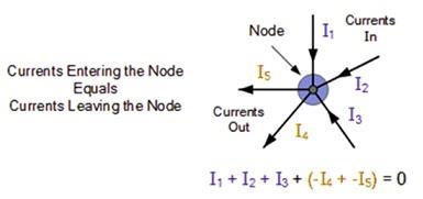
• Kirchoff's first and second rule
Kirchoff's first rule
Kirchoff's first law is also referred as kirchoff's current law. The law says that when there is no charge lost then the total current incoming to a point or junction and the current outgoing from the point is equal.
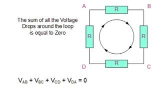
Kirchoff's second law
Kirchoff's first law is also referred as kirchoff's voltage law. According to the law, the voltage of the closed loop circuit is the total of each drop of voltage. The sum of closed loop circuit voltage is equal to zero.
Example
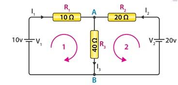
Based on first law,
At the point A and B,
I1 + I2 = I3
Based on second law,
Loop 1 gives the following,
10 = R1 x I1 + R3 x I3
= 10I1 + 40 I3
1 = I1 + 4I3
Loop 2 gives the following,
20 = R2 x I2 + R3 x I3
= 20I2 + 40 I3
1 = I2 + 2I3
Loop 3 gives the following,
10 - 20 = 10 I1 - 20 I2
1 = -I1 + 2I2
From the equation I1 + I2 = I3,
Substituting the values of loop1 in to the equation I1 + I2 = I3,
Loop 1 turns into
1 = 5I1 + 4I2
Loop 2 will be,
1 = 2I1 + 3I2
I1 = -1/3 I2
From the loop 3,
1 = 1/3 I2 + 2I2
I2 = 0.429 A
I1 = -0.143 A
I3 = 0.286 A
• Ohm's law V=IR
Current, resistance and voltage are the basic elements of electricity. The correlation between these basic elements is shown with Ohm's law.
V=I x R
Voltage (V)=Current (I) x Resistance (R). The measurement unit for resistance (R) is ohms. It is denoted with Ω. The law states that, the voltage is proportional to the current passing in between two points.
Example
Finding the electrical circuit'sresistance with the known values such as voltage V is 20 volts and the current is 10mA.
V=I x R
R=
=
=20,000 Ω= 20 kΩ
Power: P=IV, P= I2R
P=IV
The electric power (P) is the product of current (I) and Voltage (V). Power is measured using the unit called watts.
Example:
Calculating the maximum power of circuit in car which as the power outlet with the current of 30 amperes and the voltage is 12V such as.
P=IV
P= 30 A x 12 V= 360 W
Ohm's law
V=I x R
Substituting ohm's law into the equation P=IV, we get P=I2R
• Charge Q=It
Electric charge (Q) is denoted with Q=It where I is the current and the t is the time.
Electric charge is the product of current and the time. The greater amount of current at specific time yields more flow of electric charge. Coulombs is the unit for measuring electric charge. Each electron can carry electric charge of 1.6 x 10⁻¹⁹ C. There are two types of electric charges such as positive and negative. Protons are the most responsible entities for positive charge as well as electrons are more responsible entities for negative charge.
• Conductance : G= 1/R = 1/V
Conductance and the resistance are the two basic concepts for the smooth electrical current flow. Conductance and resistance are having the opposite relationship such as G=1/R where G is the conductance and R is resistance. Conductance is the task of tracking the flow of electricity easily through electrical components along specific path. The unit for measuring conductance is Siemens. The former unit is mho. Many factors decide the conductance of conductor such as dimension, shape and material property.
Example:
The resistance of circuits is 1.25 X 10³ ohms. Then the conductance of the circuit will be the reciprocal of the resistance value.
G= 1/1.25 x 103 ohms =0.8 x 10³Siemens
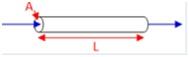
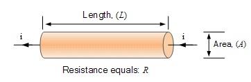
• Resistivity R= ρl/A(Ωm)
Resistance is based on the following elements such as
Length (L)
Wire thickness (A)
Material type (ρ)
Resistance R is measured using the unit Ω
Resistivity is measured using the unit Ωm
Length Lis measured using the unit m
Wire thickness Ais measured using the unit m2
Example:
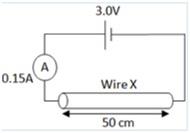
For the above given scenario, the resistivity to be calculated with the given key factors such as the wire length is doubled. The cross sectional area of the wire is halved.
Ohm's law
V=I x R
R= V/I
= 3.0/0.15= 20Ω
A=pi * r * r
A=3.14 * 0.005/2*0.005/2= 1.96 x 10⁻⁵
R= ρl/A (Ωm)
Substitute R = 20Ω value and A value into the above equation,
20=ρx0.5/(1.96 x 10-5)
=7.85 x Ωm
• Charge stored by a capacitor Q=CV
The charge stored by the capacitors Q is denoted by the unit coulombs. C is the capacitance. It is referred by the unit called Farads and V is the voltage. It is denoted by the unit called Volts.
The capacitor for storing the charge is based on the ability of the capacitors capacitance. The value of the capacitance is depends upon the area dimension of the plate and the dielectric properties of the plates. The measure for the dielectric property is . The capacitance is also referred with the following equation
C = Q/V = ε A/d
Example
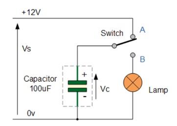
Calculation of Q value for the above circuit is given below,
Q=C x V
Q= 100 F x 12 V= 1.2 x = 1.2 mC
• Calculation of Capacitance
Parallel circuits
CT = C1 + C2
parallel circuit, the capacitors are arranged across or side by side. The sample connection of capacitors are shown below
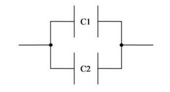
The overall capacitance of the circuit is the sum of each capacitance of capacitor in the circuit.
Example
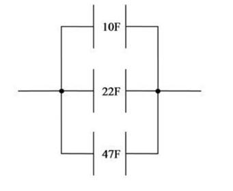
The total capacitance of the circuit is 10+22+47 = 79 Farads
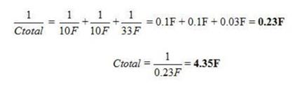
Series circuits
1/CT = 1/C1 + 1/C2
In series circuit, the capacitors are arranged one after the other. An example for series circuits is illustrated in the below diagram,
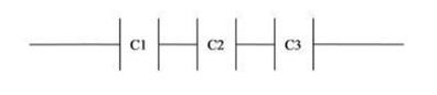
Example:

Finding the overall capacitance for the given circuit is illustrated below
NEVER BE CAUGHT IN PLAGIARISM, AVAIL ELECTRICAL CIRCUITS AND THEIR APPLICATIONS ASSIGNMENT HELP SERVICE OF EXPERTSMINDS.COM AND SAVE HIGHER MARKS!
Choose suitable examples of materials and their uses in order to provide an illustrated explanation of the properties of the following: conductivity, resistivity, insulators and conductors, ohmic and non-ohmic conductors, capacitors acting as filters in AC circuits and semi-conductors.
Section 3: Electrical Properties and uses of Materials
This section will describe that electrical properties
Resistivity and Conductivity:
Resistivity is the behaviour of a components that it stops the flow of electric current. Conductivity of a components shows how well a current is carried by the medium.
Electrical properties
The Cross section area of a material is high denotes that more conductivity is possible and thin will have a vice versa effects.
The Conductor length shall be short to carry more current in high rate
Increase in temperature in materials will lead to less movement in the materials and thus avoid the flow of conductivity and increases the resistivity.
The resistivity of the conductor materials is also having an impact on the conductivity
R = ρ(L/A) Ω
Where R is the resistance, L is length of conductor and A-Area of the conductor
Insulator and Conductor:
• Conductor will have a conducting properties eg. Copper. The outer electrons are free and move randomly. Where as in Insulator the outer electrons are not free and seems to be so tightly bounded
• Electrons flow free in conducting material and this flow is electric current. The force that is exerted in the material is called voltage.
• Insulator helpus and does not carry current. Eg. Rubber, plastic and wood etc.,
Materials Characteristics:
• Conductors have a good thick shape with increase in temperature and size is being shorter to the length.
• Organic Molecules are good properties of insulator with covalent bonds being stabilised in the environment
Ohmic and non Ohmic Conductors
Ohmic conductor exhibits linear relationship with V and I, whereas Non Ohmic does not follow Ohms law and will have a different curve.
Non Ohmic are bulb, diodes, tubes.
Temperature fully dependent on the conductor and affects the current and resistance in Ohmic conductors. Static Resistance is observed.
Non Ohmic is has not much impacted by temperature. Dynamic resistance is observed.
Capacitor as filters in AC and Semiconductor
Filter circuit has capacitor acting as high pass filters to block the DC and allow the high frequency signals. It will be placed in parallel.
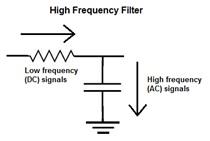
Capacitor will be used a filter in AC circuit to remove the ripples. Capacitive Reactance will be opposition to flow of current in AC circuit.
Xc = 1/2Πfc
In which Xc is reactance capacitive
F-Frequency,
C-Capacitance
Unit is Farads
ORDER NEW COPY OF ELECTRICAL CIRCUITS AND THEIR APPLICATIONS ASSIGNMENT AND SECURE HIGHER MARKS!
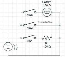
Accurately construct a circuit with the following resistors (in turn) connected in series with a switch and power source: Constantan wire, a commercial resistor and a filament light bulb. Connect an ammeter and voltmeter and record the voltage and current over a range of values for voltage. Use a table to present your readings.
Section 4: Experiments1: Ohmic and non Ohmic behaviour
Based on the Requirement the circuit is drawn as given below.
Where we have SW1 to enable Commercial Resistor R1=100Ω,
When SW2 is enabled we can have Constantan Wire to be closed
When SW3 is enabled the Lamp1 is connected to the circuit and it will be closed.
Measurement of current and voltage for the Resistor R1
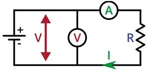
By connecting the voltmeter in parallel and Ammeter in Series to the Resistor (R1=100Ω)
Ideal VI Curve for the R1
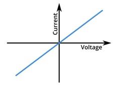
We could see the ohmic law V=IR, in the ideal case, we have V is directly proportional to Current. Also we see the linear characteristics is observed with constant temperature. V is drawn as straight line with Slope of 1/R and I is shown towards the graph.
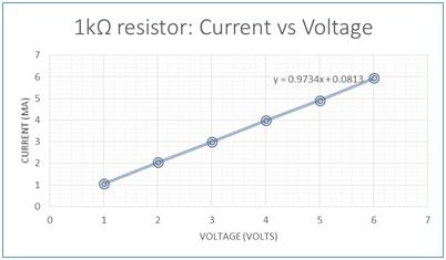
Commercial resistor:
We could observe that the IV curve is different from the Ideal curve, since the resistor (1kΩ) would have a temperature impact and curve will be nonlinear and will exhibit as shown below.
With Bulb connected with SW3 enabled and measured the values and plotted the IV curve as shown below
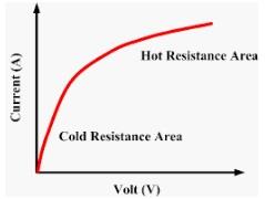
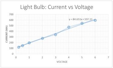
In this case initially we have cold Resistance area and curve would exhibit the Ideal part as the temperature would increase the VI curve goes to the nonlinear and show the different curve. As the current flow is bulb is high at later point, filament heats up and makes the electrons lattice not to flow one part to other. Hence this make the less ohmic characteristics.
Also non ohmic VI curve is as shown below
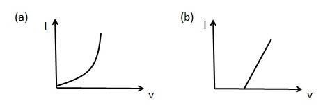
Figure a) for Diode characterises which shows the VI curves and non-linear pattern
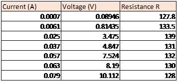
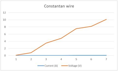
Constantan wire: It shows the ohmic Properties in the VI curve as shown in the below table.
The calculated values for I and V are calculated as table and ohmic is clearly represented.
GETTING STUCK WITH SIMILAR ELECTRICAL CIRCUITS AND THEIR APPLICATIONS ASSIGNMENTΩ ENROL WITH EXPERTSMINDS'S ELECTRICAL CIRCUITS AND THEIR APPLICATIONS ASSIGNMENT HELP SERVICES AND GET DISTRESSED WITH YOUR ASSIGNMENT WORRIES!
Section 5: Experiments2: Resistance in Series and Parallel circuits
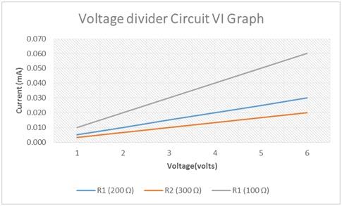
Use three resistors (100Ω, 200Ω and 300Ω) in series, parallel and combined circuits, by comparing measured values of voltage and resistance to your predicted values of voltage and resistance.
Calculate the total resistance of the circuit at each voltage and compare it to predicted value of total resistance.
Solution:
Circuit 1: Series Connection
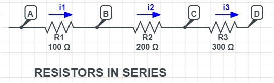
Formula to calculate the total resistance RT =R1+R2+R3=100+200+300=600Ω
Voltage drop with battery 6 V, we have the total current drawn in the circuit is
I=V/R=6/600=0.01 A=10mA is drawn across all the resistors
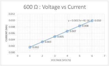
DC Sweep graph for the Series circuit for All three resistors
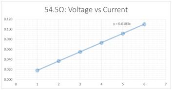
Circuit 2: Parallel connection
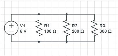
Formula to calculate the total resistance RT =1/R1+1/R2+1/R3=1/100+1/200+1/300=54.5Ω
With 6V battery, the total current drawn is I=V/R=6/54.5=0.11A=11mA
Individual current drawn are calculated by using individual resistance
Current (I1) at R1=6/100=0.06A=6mA
Current (I2) at R2=6/200=0.03A=3mA
Current (I3) at R3 =6/300=0.02A=2mA
DO WANT TO HIRE TUTOR FOR ORIGINAL ELECTRICAL CIRCUITS AND THEIR APPLICATIONS ASSIGNMENT SOLUTIONΩ AVAIL QUALITY ELECTRICAL CIRCUITS AND THEIR APPLICATIONS ASSIGNMENT WRITING SERVICE AT BEST RATES!
Section 6: Experiments 3: Capacitors in Series and Parallel circuits
Accurately construct simple circuits containing three capacitors and a power pack, firstly with the capacitors in series and then in parallel.
Solution:
Circuit 1: Capacitor in Parallel
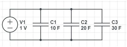
Let us consider C1=10F, C2=20F and C3=30F
The Capacitance for this circuit will be calculated as given below
Total Parallel Capacitance of this circuit is CT= C1+C2+C3=10+20+30=60F
Hence the Total Capacitance of the circuit is sum of all the Capacitance in the network, which is higher than the individuals.
Circuit2: Capacitance in Series
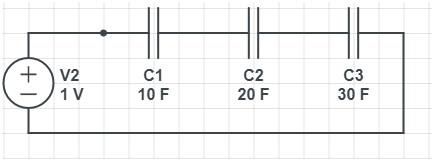
As the Capacitance in the Series we have considered and the values as
C1=10F
C2=20F
C3=30F
Total Capacitance of the circuit CT=1/ (1/C1+1/C2+1/C3)=5.45F
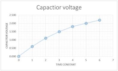
Inference: The total Capacitance of the circuit is less on the other components in the circuit.
GET GUARANTEED SATISFACTION OR MONEY BACK UNDER ELECTRICAL CIRCUITS AND THEIR APPLICATIONS ASSIGNMENT HELP SERVICES OF EXPERTSMINDS.COM - ORDER TODAY NEW COPY OF THIS ASSIGNMENT!
Section 7: Experiments 4: Potential Divider Circuit
Research how to build voltage divider circuits and demonstrate through experiment how to divide a 6.0V power output into 1V, 2V and 3V using three resistors.
Solution:
Based the given requirement the circuit is drawn
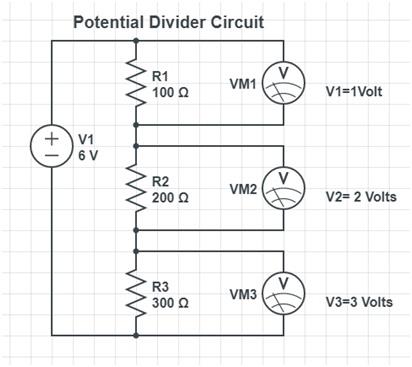
Voltage Across Resistor RN = (VIN)RN/R1+R2+R3+.....
Voltage divider circuit voltage drop is calculated based on the Kirchoff`s laws.
As we need the v1=1 volt, v2=2 volts and v3=3 volts
Vout at R1= Vin(R1/R1+R2+R3)=(6*100)/(100+200+300)=1V
Vout at R1= Vin(R1/R1+R2+R3)=(6*200)/(100+200+300)=2V
Vout at R1= Vin(R1/R1+R2+R3)=(6*300)/(100+200+300)=3V
Hence this shows that R1=100Ω, R2=200Ω and R3=300Ω
Limitations of Potential divider circuit will be using of large resistance values will cause output impedance higher and causes the output voltage to be variation based on load conditions. Also Sensitivity to the mechanical components stress developed.
It is recommended to use the potentiometers and variable pots to get the accurate values and with low values.
ORDER NEW ELECTRICAL CIRCUITS AND THEIR APPLICATIONS ASSIGNMENT & GET 100% ORIGINAL SOLUTION AND QUALITY WRITTEN CONTENTS IN WELL FORMATS AND PROPER REFERENCING.