GET ASSURED A++ GRADE IN EACH FREQUENCY DIVISION MULTIPLEXING ASSIGNMENT ORDER - ORDER FOR ORIGINALLY WRITTEN SOLUTIONS!
Lab - Frequency-Division Multiplexing from the Communication Systems
Objective - In this laboratory exercise you will investigate sending multiple messages on a single carrier by frequency-division multiplexing. Each individual message is modulated onto a separate subcarrier and the modulated subcarriers are summed before being sent to the USRP. At the receiver, the individual messages are separated by filtering and then demodulated. The purpose of this exercise is to:
- provide additional practice in programming the USRP,
- introduce the concept of frequency-division multiplexing, and
- explore the concept of intermediate-frequency filtering in the receiver.
Answer - Starting with Eq. (5), show analytically that the phase error θ does not affect either demodulated output signal. Note that in this lab project we do not take the real part of r(t) prior to bandpass filtering
Equation 5 is given as: r~(t) = D[g1(t) + g2(t)]ejθ,
where theta is the stage distinction between the transmitter and recipient oscillator sign and D is a consistent, generally a lot littler than A This complex-esteemed sign can be sent to a bank of two bandpass channels fixated on the subcarrier frequencies f1 what's more, f2. The channel yields are the individual flag These would now be able to be demodulated utilizing envelope indicators.
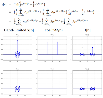
Try to apply the heterodyne standard by and by: duplicate the got sign by a nearby sinusoidal sign that is indistinguishable from the bearer! An exquisite method to perceive what might happen is to begin with Figure , as opposed to the time-area portrayal. We presently can imagine that we have a "baseband" signal whose recurrence parts are as demonstrated , and what we're doing now is to "blend" (i.e., increase) that with the carrier.We can as needs be take every one of the two (i.e., genuine and fanciful) pieces in the right-most column of and treat each thus The outcome is appeared above . The left section demonstrates the recurrence components for the first (formed) baseband signal, x[j]. The center section demonstrates the frequency components of the tweaked sign, t[n], which is equivalent to one side most segment of. The transporter (cos(35ω1n), so the DTFS coefficients of t[n] are revolved around k = -35 and k = 35 in the center section. Presently, when we blend that with a nearby signal indistinguishable from the bearer, we will move every one of these two gatherings of coefficients by ±35 once once more, to see a bunch of coefficients at -70 and 0 (from the -35 gathering) and at 0 and +70 (from the +35 gathering). Each piece will be scaled by a further factor of 1/2, so the left and right bunches on the right-most segment in Figure 14-7 will be 1/4 as huge as the first baseband segments, while the center bunch focused at 0, with a similar range as the unique baseband signal, will be scaled by 1/2.
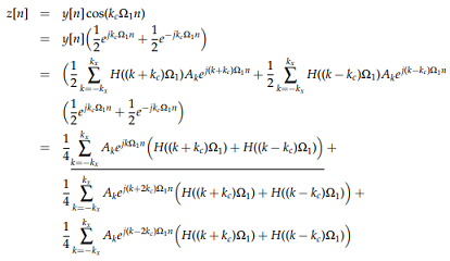
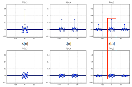
How might we recuperate this center piece alone and disregard the left and right bunches, which are focused at frequencies that are at double the bearer recurrence in the positive and negative headings? We have effectively considered a method in previous chapter: a low-pass channel. By applying a low-pass channel whose cut-off recurrence lies among kx and 2kc - kx, we can recuperate the first signal reliably. We can arrive at similar determinations by doing an increasingly careful estimation, like the estimations we accomplished for the regulation, prompting. Let z[n] be the sign acquired by duplicating (blending) the neighborhood imitation of the transporter cos(kcω1n) and the got signal, r[n] = t[n], which is obviously equivalent to x[n] cos(kcω1n). Utilizing Equation 14.3, we can express z[n] as far as its DTFS coefficients as pursues.
NO PLAGIARISM POLICY - ORDER NEW FREQUENCY DIVISION MULTIPLEXING ASSIGNMENT & GET WELL WRITTEN SOLUTIONS DOCUMENTS WITH FREE TURNTIN REPORT!
The calculation can be shown as:
The center term, underlined, is the thing that we need to separate. The principal term is at double the bearer recurrence over the baseband, while the third term is at double the transporter recurrence underneath the baseband; both of those should be sifted through by the demodulator
Channel distortion
Frequency demodulation then:
Question - Submit AMonSubcarrier.gvi and the functions you created for the transmitter and receiver. Also submit any additional sub-functions you may have created. Be sure your files adhere to the naming convention described in the instructions above. Resubmit documentation for any functions you modified during the lab. Submit the spectrum graph required in Step 4 and all of the crosstalk information required in Step 5 of the Lab Procedure.
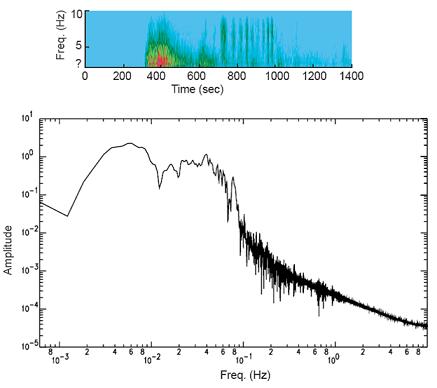
Spectrum graph
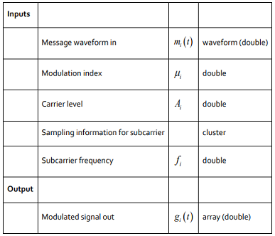
The input and output is given as
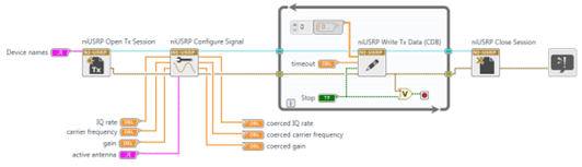
Transmitter template configuring Signal is utilized to set parameter esteems in the USRP. Append four controls and three markers to this capacity as appeared in the figure. To begin, set the IQ rate to 200 kSa/s (the most minimal conceivable rate), the bearer recurrence to 915.1 MHz, the increase to 0 dB, and the dynamic reception apparatus to TX1. At the point when the capacity runs, the USRP will restore the real estimations of these parameters. These qualities will be shown by the markers you associated. Ordinarily the genuine parameter esteems will coordinate the ideal qualities, yet on the off chance that at least one of the ideal qualities is outside the ability of the USRP, the closest worthy parameter worth will be picked, as opposed to restoring a mistake Compose Tx Data composes the baseband sign to the USRP for transmission. Putting this capacity in some time circle permits a square of baseband sign examples to be sent again and again until the "stop" catch is squeezed. Note that the while circle is modified to end if a blunder is distinguished. Baseband sign examples can be given to the Write Tx Data as either a variety of complex numbers or as a mind boggling waveform information type. The Configure strip at the highest point of LabVIEW Correspondences enables you to pick the information type
ENDLESS SUPPORT IN FREQUENCY DIVISION MULTIPLEXING ASSIGNMENTS WRITING SERVICES - YOU GET REVISED OR MODIFIED WORK TILL YOU ARE SATISFIED WITH OUR FREQUENCY DIVISION MULTIPLEXING ASSIGNMENT HELP SERVICES!
For the transmitter
In this expression, the constant A is set by the "gain" parameter and fc is the carrier frequency. The sampling interval Tx is the reciprocal of the "IQ rate". Note that the signal g(t) produced by the USRP is a continuous-time signal; the discrete-to-continuous conversion is done inside the USRP.
Observe that the baseband signal g~(nTx) is actually two baseband signals. By long-standing tradition, the real part gl(nTx) is called the "in-phase" component of the baseband signal and the imaginary part gQ(nTx) is called the "quadrature" component of the baseband signal. The AM signal that we will generate in this lab project uses only the in-phase component, with
gl(t) = A[A + μ(m(y)/mp)],
and
gQ(t) = 0.
Receiver Template
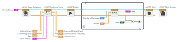
Bring Rx Data recovers the message tests gotten by the USRP. Setting this capacity in some time circle permits message tests to be recovered each square in turn until the "stop" catch is squeezed. Note that the while circle is customized to end if a blunder is distinguished. "Various tests" control enables you to set the quantity of tests that will be recovered with each pass through the while circle. In later lab extends in this arrangement, we won't utilize the while circle, and will bring just a solitary square of information from the collector. Bring Rx Data can give message tests to the client as either a variety of complex numbers or as an intricate waveform information type. A draw down tab enables you to pick the information type for the message tests.
GET READYMADE FREQUENCY DIVISION MULTIPLEXING ASSIGNMENT SOLUTIONS - 100% PLAGIARISM FREE WORK DOCUMENT AT NOMINAL CHARGES!