GET ASSURED A++ GRADE IN EACH DIGITAL CONTROL SYSTEM ASSIGNMENT ORDER - ORDER FOR ORIGINALLY WRITTEN SOLUTIONS!
Assignment - Digital Control System and PLC
Question 1: What refers Resolution to the analog to digital conversion portion of a digital control system?
Answer - Resolution means the no. of distinct-values that used to yield over the analog value. It also measures the magnitude of the quantization error, the maximum possible average signal-to-noise ratio for an ideal ADC without the use of oversampling. The values are usually stored electronically in binary form.
Suppose, ADC having a resolution of 4 bits can be encoded an analog I/P to 16 unlike levels (24 = 16). The values can be then represented in unsigned integer, ranges from 0 to 15 or signed integer,from -8 to 7, based on the requirement.
The other form of resolution is voltage resolution which can be defined as the ratio of overall voltage range to the interval number, and expressed as follows:
Q = EFSR/2M
Where M = resolution of ADC (in bits) and EFSR = span.
Question 2: What is a typical use for an integer variable in a digital control system?
Answer - An integer which is used as variable defines the count of discrete events.
Question 3: Identify the problem in this motor control PLC program.
ANSWER - Given motor control PLC program:
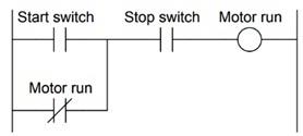
Problem no. 1: to activate Motor run it is required to ON both Start switch and Stop switch, as they are both NO (Normally Open) type switch. That means Seal-in contact.
Problem no. 2: Motor run switch is NC (Normally Closed) type, thus no use of Start switch occurred and Stop switch required to ON to activate Motor run.
NO PLAGIARISM POLICY - ORDER NEW DIGITAL CONTROL SYSTEM ASSIGNMENT & GET WELL WRITTEN SOLUTIONS DOCUMENTS WITH FREE TURNTIN REPORT!
Question 4: Determine the switch actuation statuses (i.e. low versus high process stimulus) given the "live" display of the ladder logic program. Also, determine the status of the lamp connected to the PLC's Y1 output.
Answer - Given Diagram:
Switch actuation statuses:
The Switch actuation status is Low-flow,High-pressure and low- temperature.
The ladder logic program:
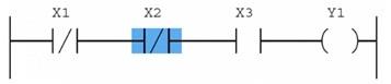
Status of the lamp which is connected to PLC's Y1 output:
Lamp will be de-energized.
To energize the lamp, pressure and flow should be high and temperature should be low.
ENDLESS SUPPORT IN DIGITAL CONTROL SYSTEM ASSIGNMENTS WRITING SERVICES - YOU GET REVISED OR MODIFIED WORK TILL YOU ARE SATISFIED WITH OUR DIGITAL CONTROL SYSTEM ASSIGNMENT HELP SERVICES!
Question 5: Identify the type of contact (either NO or NC) necessary for each of these electrical switch contacts, based on the trip condition (either high or low) and how each input is applied in the PLC program.
Answer - Given PLC program:
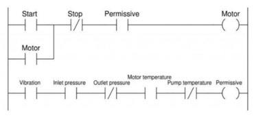
Identification of the contact type:
1. Start pushbutton = NO
2. Stop pushbutton = NO
3. High vibration = NC
4. Low inlet pressure = NO
5. High outlet pressure = NO
6. High motor temperature = NC
7. High pump temperature = NO
The permissive condition that is required for correct operating conditions shown in following figure:
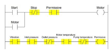
The coloured parts allow the motor to run.
The NO Permissive contact in the upper rung needs to be coloured if the Motor coil receive colour. This signifies that the entire series string of contact orders, present in second rung needs to be coloured under proper operating conditions.
High Vibration: As Permissive is NO (normally open) type, PLC I/P must be activatedaccording to colouring order.
The High Vibration switch must be in the closed condition when everything is running condition as it is in low vibration, and open if vibration becomes extreme.
The NC (Normally Closed) vibration switch is closed when vibration is lower the trip threshold.
Low Inlet Pressure: As Permissive is NO (Normally Open) type, PLC I/P must be activated according to colouring order.
Low Inlet Pressure switch must be in the closed condition when everything is running condition as it is in adequate inlet pressure, and open if Inlet Pressure becomes very low.
When pressure is below the trip threshold, the NO (Normally Open) pressure switch is open.
High Outlet Pressure: As Permissive is NC (Normally Closed) type, PLC I/P must be de- activated according to colouring order.
The High Outlet pressure switch must be in the open condition when everything is running condition as it is in moderate Outlet pressure, and close if vibration becomes extreme.
The NO (Normally Open) pressure switch is open when pressure is lower the trip threshold.
HELPING STUDENTS TO WRITE QUALITY DIGITAL CONTROL SYSTEM ASSIGNMENT AT LOW COST!
Question 6: Indicate the order in which the following steps should occur when troubleshooting a PLC input:
__4___ check the wiring connection to the module
__2__ close the field device and measure the voltage to the input module
__5___ place the PLC in standby mode
__1___ evaluate the PLC's reading of the module
__3___ check for voltage at the field device
Answer - The five common methods for trouble shooting the PLC systems:
1. Troubleshooting ground loops: In this method maintain stock of replacement parts.
2. Diagnostic indicators of PLC: Normally, indicators are provide information about devices that placed in field, wiring of that's, I/O modules. Every I/O module has at least one indicator such as power indicators are used as I/P indicators and logic indicators are used as O/P indicators.
3. Troubleshooting PLC inputs: I/P indicators gives information about the part, the device and it's wiring pinpoint problem.
Initially, PLC place in standby mode, thus output is not activated. Thenevaluate I/P reading of the PLC.
4. Troubleshooting PLC outputs: Initially, outputs are isolated the difficult to either the part, the device or wirings.
5. Troubleshooting CPU: The indicators should include power, memory status.
GET READYMADE DIGITAL CONTROL SYSTEM ASSIGNMENT SOLUTIONS - 100% PLAGIARISM FREE WORK DOCUMENT AT NOMINAL CHARGES!