ANSYS CFD FINS
301023 Advanced Thermal and Fluid Engineering, Western Sydney University, Australia
DON'T MISS YOUR CHANCE TO EXCEL IN ENGINEERING ASSIGNMENT! HIRE TUTOR OF EXPERTSMINDS.COM FOR PERFECTLY WRITTEN 301023 ADVANCED THERMAL AND FLUID ENGINEERING ASSIGNMENT SOLUTIONS!
Introduction: So as to comprehend the rudiments of Heat exchange it very well may be ordered in to some exceptionally essential and key definitions, and recognizing what recognizes temperature and Heat, Thermodynamics and techniques or methods of Heat exchange.
Question 1: If the air flow velocity at the inlet is 1 m/s and the air temperature is 20°C. The fins are parallel to the x-direction in Figure 1, find out which of the follow configuration leads to the lowest temperature on the fin:
a. The centres of the inlet and outlet ducts are 70 mm above the bottom.
b. The centres of the inlet and outlet ducts are 850 mm above the bottom.
c. The centres of the inlet and outlet ducts are 100 mm above the bottom.
Question 2: Using the best height of the air duct found in question 1, find which of the following configuration has the lowest temperature on the fin:
a. The fines are parallel to the x-direction.
b. The fins are parallel to the y-direction.
Answer: Temperature: The vitality that is conveyed by the atoms, it can likewise be characterized as the degree to which a substance is hot or cold, it can stream in or out of a framework that makes it directional amount, so it can likewise be characterized as far as the heading marker of exchange of Heat. It is indicated by the image T. The units used to quantify this amount are Degrees Centigrade (?), Kelvin (K) or Fahrenheit (?).
Heat: In actuality the Heat is really stream of vitality. It as a rule goes from a more smoking body to a colder one. It is meant by the image Q. The units used to quantify this amount Calorie or Joule.
Thermodynamics manages: • Extent of heat exchanged ?Q
• The amount of work that is done by/on the system ?W
• The System at its procedure culmination state.
Heat exchange manages: • The strategy for Heat exchange ?Q
• Heat Exchange rate ?Q
• Allocation of temperature in the entire system
We can exchange heat by three modes, which are conduction (for solids), convection (via radiation) and convection (in the case of fluids)
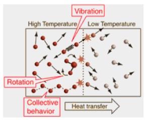
Heat Transfer in Solids: Conduction: The vitality exchange crosswise over limits of two frameworks at various temperatures, this Heat transmission happens by bury sub-atomic cooperation while it doesn't require any mass movement however the vibration attributes of particles. Condition is expressed as
Qcond. = kA(dt/dx) → Eq. 1
Here, we have:
Qcond. = heat transfer rate (Watts).
k = Thermal conductivity, which is the heat transferred at unit temperature (W/mK).
A = Heat flow area (m2).
dt = a small temperature (K).
dx = material thickness (m).
SAVE YOUR HIGHER GRADE WITH ACQUIRING 301023 ADVANCED THERMAL AND FLUID ENGINEERING ASSIGNMENT HELP AND QUALITY HOMEWORK WRITING SERVICES OF EXPERTSMINDS.COM!
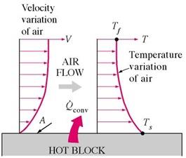
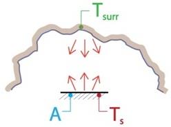
Heat Transfer in Liquids: The vitality exchange over the limits of a framework because of atomic collaboration with the fluid moving over the substance or example under investigation, Convection happens when the issue is fluid and consistently streams normally or by power. The driving component in convection is likewise temperature contrast. This distinction in temperature causes Heat exchange until the bodies are totally at warm harmony with one another. The adjustment in temperature causes change in densities of substance while explicitly in convection the more blazing air rises while cooler air settles down helping the Heat exchange from a more sweltering space to cooler.
From the below expression, we can determine the convective heat exchange;
Qconv. = h.A(t1 - t2) → Eq. 2
Here, we have:
Qconv.= Convective mode of heat transfer (in Watts)
h = coefficient of heat exchange (W/m2K)
A = Heat flow area in (m2).
(t1 - t2) = The variation in the temperature from section 1 to 2 in (K).
Electromagnetic Heat Transfer: Vitality that is exchanged crosswise over limits of a framework because of exchange of Heat by electromagnetic radiations that becomes possibly the most important factor as a result of the temperature of the body. Radiation needn't bother with any mode or middle for Heat Exchange;
Qrad. = σ.A.T4 → Eq. 3
Here:
Qrad. = Radiation-based heat exchange (watts)
σ = Stefan-Boltzmann constant
A = Area exposed to heat exchange (m2)
T = A absolute for radiation (K)
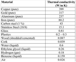
Thermal Conductivity: As we realize that the warm conductivity is the is property of thermodynamics that manages autonomous properties that are concentrated in nature that are weight and temperature, aside from the gases which are genuine where the general reliance in just on temperature and is free of escalated property
Where K (Thermal conductivity) depends upon the temperature
Proclamation: In this task it is to be considered that the thirteen blades with a strong base of 4mm and each 2mm thick is seen to have been put before a fan where air delta speed of 1m/s streams over these balances at variable statures and balance arrangements, it is to be contemplated what of the conduct of temperature appropriation to the progression of air is most reasonable for a viable circumstance and above all in fact suitable, Heat exchange over balances has been a territory of perception and viable reenactments have been performed for most productive plans. The plan under thought has its geniuses over different shapes and designs of blades, under the limit conditions set and fluid contact surface with balances are set up it is a major idea under investigation. We will see into the temperature dissemination for the air inlet and different designs of blades to discover the most appropriate choice for a useful case while toward the end the outcomes would be finished up and suggestions are to be given.
ORDER NEW 301023 ADVANCED THERMAL AND FLUID ENGINEERING ASSIGNMENT AND GET 100% ORIGINAL SOLUTION AND QUALITY WRITTEN CONTENTS IN WELL FORMATS AND PROPER REFERENCING!
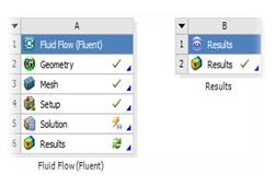
Strategy: Computational fluid elements have been a key apparatus for reproduction and near ongoing guess of any article's conduct. Key components of a Thermal CFD recreation are:
1. Characterizing geometry: a. Collect and create, Boolean, Subtraction of source from fluid locale, produce for complete body review and continue
2. Cross section: a. Include technique, contact measuring for work size control and Mesh
3. Mesh creation: a. Named choice for Inlet, outlet, fluid and source are included.
4. Setup: a. Ste-up a configuration to get appropriate velocity, pressure and determine whether the system is transient or steady.
5. Model: a. As per energy eqn. I and viscous k-epsilon equation we will determine the wall function
6. Materials: a. Properties of the material that is used as indicated by the chose or under examination material
7. Cell zone conditions: a. Fluid should be characterized as air and source with the power age esteem included.
8. Limit condition: a. Gulf, outlet and divider to be given speed, weight and no slip divider conditions individually with warm property expansion of convection
9. Solution: a. Arrangement Initialization, Calculation Activities, Running Calculation with time steps and cycles.
Given Parameters: In the Given conditions it is seen that a balance with 100W power age limit is presented to constrained air from a fan with delta air speed at 1m/s while temperature of air at entering is 20 degree Celsius. The limit conditions set with bay pipes at statures of 100, 85 and 70 mm separately from the base of the bouncing conclusion.
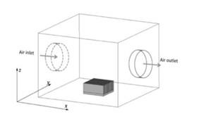
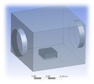
Bounding box
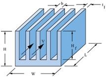
Fins
The statures are imperatively significant for the stream over blades, as the Heat exchange relies upon the measure of fluid for convection and the rate of stream over the subject, more the mass flow-rate over the body more prominent will be the Heat transmission, comparatively more noteworthy the season of collaboration more noteworthy will be the Heat transmission so Heat Transfer here is legitimately corresponding to speed of the fluid over balances, and the territory. Along these lines, for ideal Heat exchange there ought to be a tallness of gulf and outlet channel where Area of collaboration is most extreme and Velocity is least for ideal. Heat exchange among source and the fluid space.
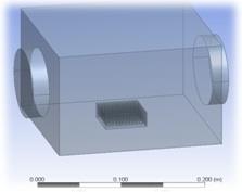
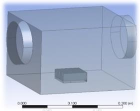
CAD (Computer Aided Design): In the CAD for in advance of referenced get together, the setups of blades, statures of pipes are demonstrated at various statures, balances can be set in two arrangements either parallel to the x-pivot or y-hub. The Heights for channel asked are 70mm, 85mm and 100mm while it is regularly great to think about that structure parameter and plan limitations are instituted and sensible areas are characterized so as to accomplish precise outcomes. A few parameters that are to be considered for this task, altogether significant parameters and contemplations are Height of Inlet and outlet, X-Y hub arrangement of blades, Surface territory and introduction time
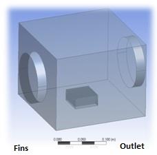
Fig 1. Ducts at 70mm
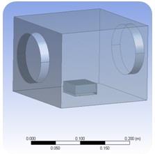
Fig.2 Ducts at 85mm
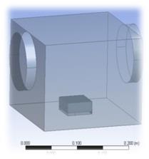
Fig.3 Ducts at 100mm
Statures of Air Inlet/Outlet: In all these figures, the heights of the ducts are 70 mm, 85 mm and 100 mm respectively.
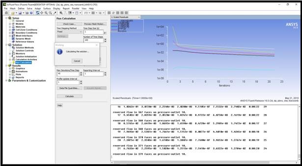
Ansys has an exceptional space structure for each venture or reproduction, however in the present situation, every reenactment is remarkable and has nothing to do with the other arrangement results aside from the end and correlation hypothetically. Every reenactment is performed independently because of progress in geometry without fail.
In the Fig.4 the setup for one specific case can be viewed.
EXPERTSMINDS.COM GIVES ACCOUNTABILITY OF YOUR TIME AND MONEY - AVAIL TOP RESULTS ORIGINATED 301023 ADVANCED THERMAL AND FLUID ENGINEERING ASSIGNMENT HELP SERVICES AT BEST RATES!
Ways for which the Optimum Heat Transfer can be facilitated:
Allocation of ducts above 70 mm w.r.t. the base and parallel placed from the x-axis:
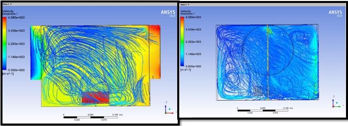
As per the philosophy for ANSYS reproduction referenced before, the geometry for first case is picked and Thermal CFD investigation is played out, this design as found in the fig demonstrates that balances are parallel to x-hub while conduits are right now at a stature if 70mm.As the balances are presently nearest to the fluid and are parallel to air stream they should perform ideally alongside the temperature dispersion over the base, results are pursued..
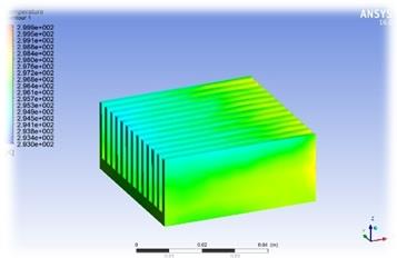
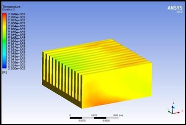
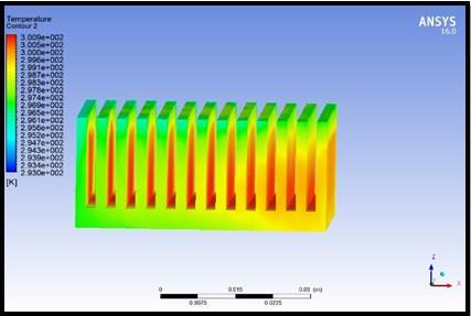
For this situation the balances being a check to the wind current from channel conduit acts as higher-weight space this outcomes into a lower speed, while the fluid moving through the balances transmission the temperature, the balances can unmistakably be seen with lower temperature at the top where streamlines go through. The general temperature isn't as high as is by all accounts having a uniform conveyance over the territory. What really occurs here is that air getting through the channel conduit streams is laminar in nature, when it hits the blades surface which is really a contact locale, the air speed drops as talked about before the immediate proportionality of surface zone just as speed becomes possibly the most important factor which fills the essential need of Heat exchange, this drops the temperature of balances while expanding temperature of the encompassing media. Presently Let us look at the focuses at various areas of the edge;
Point A: At A the air speed of the fluid has decreased, and Temperature as of now at 295K, this demonstrates in general most elevated temperature on the balance is at B for example 298.4K, where working fluid has not come to totally at 1 m/s yet halfway the conductive
Heat move has become an integral factor to keep up the balance.
Corner focuses: At the sides of bouncing box there will be a whirl and vortices are produced this is a direct result of the speed decrease and weight increment because of the nearness of balances as a hindrance.
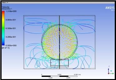
Observing the velocity streamlines in this case to clearly study the flow of fluid through fins.

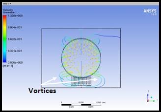
Watching the speed streamlines for this situation to unmistakably consider the progression of fluid through balances. The speed streamlines being laminar at first, united while going through blades and after that abrupt extension coming about into lessening in temperature of working fluid, this weight speed change results into a steady and nearly uniform Heat transmission. The Streamlines can be found in the left figure where the speed at the season of entering the fluid space is around a normal of 0.9m/s while moving along the length speed begins dropping until it scopes to 0.301m/s this shows plainly that the blades have hindered the fluid for example air anyway the Heat transmission is expanded by this drop in speed. The air a short time later grows abruptly and speed begins expanding until it spans to the outlet conduit where it has come to a limit of 1.32 m/s.
Allocation of ducts above 85 mm w.r.t. the base and parallel placed from the x-axis:
Applying the procedure once more, this design as found in the fig demonstrates that blades are parallel to x-pivot while conduits are as of now at a stature if 85mm. The blades are relatively a long way from the fluid and are parallel to air stream they should not be performing ideally in view of which the fluid probably won't come in direct contact with the balances and also the balances might not have a uniform temperature dispersion over the base.Presently there are two contemplations that must be remembered, as the fluid doesn't generally go through the blades the speed of the fluid would not lessen and there will be lesser time for Heat transmission, while then again balances temperature would include temperature to the encompassing media at a semi way. A general perception can be made that the higher gulf channel doesn't permit ideal Heat transmission for this situation.
For this situation the temperature dissemination seems, by all accounts, to be extreme and non-uniform, the base temperature is high while toward the beginning of the blades there is a base temperature of 297K, this demonstrates there is a higher temperature at the balances kept up for a delayed time and can make the apparatuses be more blazing. This may likewise demonstrate to harm for the framework.
One noteworthy perception is that the fluid leaving the framework isn't at a higher Temperature.
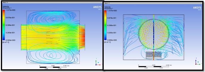
Speed Comparison plainly demonstrates that the stream is a greater amount of unguided and fierce, It can be seen that aside from the temperature the fluid is increasingly dispersed not in contact with the blades much Which means the fluid for example the diminished surface territory and high speed will in general abatement the general Heat exchange and this may result into a shaky or inordinate burden framework. We can finish up this by saying this case isn't reasonable for a mechanical apparatus. Presently a conventional perception can be made here that while the air enters fluid area it doesn't end up in contact with the balances by any stretch of the imagination, rather the fluid finds higher speed to the inside and lower speed to the external edges of pipe periphery, this distinction in weight and speed makes it very hard for the fluid to proceed in a streamlined way and it digresses making vortices, this choppiness is certainly not a decent stream for Heat transmission.
24/7 AVAILABILITY OF TRUSTED 301023 ADVANCED THERMAL AND FLUID ENGINEERING ASSIGNMENT WRITERS! ORDER ASSIGNMENTS FOR BETTER RESULTS!
Allocation of ducts (both inlet and outlet) above 100 mm w.r.t. the base and fin is parallel placed w.r.t x-axis:
Taking into account this approach once more, this design as found in the fig demonstrates that blades are parallel to x-hub while pipes are at present at a tallness if 100 mm. The blades are nearly further a long way from the fluid and are parallel to air stream they should not be performing ideally in view of which the fluid won't come in direct contact with the balances and furthermore the balances won't have a uniform temperature dispersion over the base. As there is by all accounts practically zero Heat transmission.
Further, we can make a perception that the higher gulf conduit doesn't permit at all the ideal.
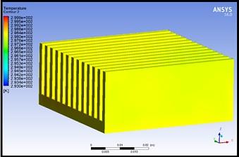
As per this figure which demonstrates that there is little to none Heat transmission between the blades and the encompassing the fluid has gently contacted the balances while no glow leaving the framework at this demonstrates to be the most noticeably awful organization thought for balances as a Heat source to be managed the air as fluid. The Design Parameters are completely countered or inversed in expressions of effectiveness as there is a little segment of balances surface territory accessible, while the air speed seems, by all accounts, to be dealing with no Heat transmission between the framework and the encompassing.
Decisively this design thought needs not to be additionally done in a pragmatic framework. The Velocity streamlines showing the fluid float being violent for example bigger speed with no express or contact region for a normal Heat transmission, thusly this case has been
refuted from the keen usage. Presently that Case one has tried to be most ominous arrangements.
Case A: Allocation of ducts (both inlet and outlet) above 100 mm w.r.t. the base and fin is parallel placed w.r.t Y-axis:
Taking into account this approach for ANSYS recreation referenced before, the geometry for first case is picked and Thermal CFD examination is played out, this design as found in the fig demonstrates that blades are parallel to Y-pivot while conduits are at present at a tallness if 100 mm. As the balances are right now uttermost to the fluid and are opposite to air stream alongside the temperature appropriation over the base, results are pursued.
Temperature Contour- Fluid Domain Case A
In the present case the balances and their tips are presented to the had relations with fluid stream with low speed and nearly lower territory contrasted with case one, the leaving Fluid also doesn't leave at a higher temperature. this recommends temperature is contained inside the framework even it's not copious in Heat transmission, comparability the fluid area has a violent conduct towards blades, the wind current isn't uniform and may require thought, likewise it very well may be seen that the balances have a higher temperature at the base this demonstrates the present arrangement doesn't bolster uniform temperature conveyance anyway may urge harm the bouncing box or components snared to it, on the grounds that the temperature seems, by all accounts, to be ascending at the edges of the jumping box.
The outcomes will most unquestionably be horribly mind boggling anyway from the investigation of designs and conduits the parametrical change has backed out the outcomes and made it easy to settle on a choice for case is most fitted and demonstrates to be best Heat transmission for the glow supply and in this manner the nearby with a great deal of breadth, lower speed and streamline stream over the length. in short clarified just on the off chance that one.
Indisputable Results: The outcomes can unquestionably be mind boggling yet from the investigation of setups and channels the parametrical change has streamlined the outcomes and made it simple to choose which case is most reasonable and demonstrates to be most effective Heat trade for the Heat source and the encompassing with progressively surface territory, lower speed and laminar stream over the length. Quickly clarified on the off chance that case one which results into a temperature conveyance uniform over the balances has least temperatures and nearly biggest region of communication with the fluid, this implies fluid with laminar stream, having traded heat appropriately among blades and fluid among three cases.
Suggestion: It is profoundly prescribed that the fluid gulf conduit is kept up at a similar tallness while outlet channel is put at the base this will build the surface region for Heat trade further and bring down the speed of the fluid too coming about into more Heat exchange between the source and the encompassing. Furthermore the balances configuration can be enhanced alongside the stature of channel and outlet conduit, so as to build the Heat exchange further, the delta pipe can be set a bit lower while balances are put in a parallel x-hub setup.
We At Expertsminds Are Delivering The Academic Services For Various Related Units And Courses Along With Our Western Sydney University, Australia Assignment Help:
301006 - Advanced Engineering Project Assignment Help
300597 - Master Project Assignment Help
301005 - Professional Practice and Communication Assignment Help
301004 - Research Preparation in Post Graduate Studies Assignment Help
301002 - Specialised Software Applications Assignment Help
301003 - Sustainable Systems Assignment Help
301187 - Managing Project Teams and Stakeholders Assignment Help
301194 - Financial Management of Projects Assignment Help
301195 - Time and Quality Management Assignment Help
301192 - Risk Management and Decision Making Assignment Help